Ten years ago (“BSI-024: Vocabulary”, October 2009) I issued a challenge regarding water control layers asking folks for ideas regarding a performance metric for water control layers. I suggested that we might need a material metric or an assembly metric or perhaps both. At the time no rational performance metric or metrics existed for a water control layer.
There were irrational ones. For example, how about requiring a water control layer (a “material metric”) to resist 25 inches of standing water (6,200 Pa – the force exerted by a 225 mph wind)? This is obviously madness (yes some products are rated this way) as housewrap products that are rated this way and pass leak when they are installed on a wall with holes created by staples and cap nails that are used to install them and through nail holes penetrating them when cladding is attached. What is the point of having a metric that assumes no holes? How would you install it? Yup, put holes in it. Or if you can get it installed without holes how do you attach stuff to it or through it? Yup, you put holes in it. Couldn’t you seal the holes after you put them in? Sometimes….but mostly take “good luck” for an answer.
But housewrap products….and water control layers in general….with holes in them do not always leak. Huh? Yes, you read that right. They don’t always leak even though they have holes….lots of holes. They can in fact have thousands of holes and not leak. You also need a driving force....hydrostatic pressure is the big one…air pressure not so much…and yes we were here before (“BSI-057: Hockey Pucks and Hydrostatic Pressure”, January 2012). Check out Photograph 1– cedar shingles nailed through a housewrap water control layer resulting in thousands of holes on a large house on the ocean in New England. But the wall assembly does not leak because the hydrostatic pressure driving force is controlled by the drainage mat installed between the cedar shingles and the mechanically attached water control layer….resulting in….wait for it…”drainage”.
Photograph 1: Thousands of Holes- Cedar shingles nailed through a housewrap water control layer resulting in thousands of holes on a large house on the ocean in New England. But the wall assembly does not leak because the hydrostatic pressure driving force is controlled by the drainage mat installed between the cedar shingles and the mechanically attached water control layer….resulting in….wait for it…”drainage”.
It was clear that if you drained the water penetrating the cladding you would control the hydrostatic pressure and small holes would not matter. This is not new news. I think Vitruvius got there 2 millennia ago[2].
The obvious “ah hah” for more than 2 millennia is that you can’t drain water on a drainage plane (aka “water control layer” or “water resistant barrier (WRB)) without a drainage space or gap. The issue for quite some time has been twofold: how big of a space or gap do you need and when do you need one.
So where am I going with this? Well, I think we now have a reasonable metric on drainage (an “assembly” metric)…and that gives us lots and lots of options because with good drainage pretty much everything works. I still don’t think we have a reasonable metric for water control layer materials (the “material” metric)….more on that later. The good news is that assembly performance trumps material performance. Always.
Time for some heresy…with a good drainage matric I don’t think we need much of a material metric for water control layers. The goal should be to get rid of the crazy metrics that restrict materials and innovative approaches…if you have good drainage.
Although we now have a reasonable metric on drainage (in my opinion) and the necessary associated drainage space or gap (in my opinion) we do not have much agreement on when we need the drainage and the gap. Some background is necessary here.
We have thousands of buildings with stucco failures to thank for the metric on drainage (Photograph 2). Yes, we were also here before (“BSI-102: The Coming Stucco-Pocalypse”, January 2018 and “The Perfect Storm Over Stucco, ASHRAE Journal, February 2008).
Photograph 2: Stucco Failure– Not a pretty sight. No drainage coupled with moisture sensitive sheathing (oriented strand board – OSB) and high levels of thermal resistance (not enough energy flow to facilitate drying).
The model building codes (International Building Code, aka “IBC” and the International Residential Code, aka “IRC”) will both have the following requirement for stucco installed over wood based sheathings in the imminent future:
“a minimum 3/16 inch space shall be provided between the stucco and water-resistive barrier or a space having a drainage efficiency of not less than 90 percent, as measured in accordance with ASTM E2273 or Annex A2 of ASTM E2925, shall be added to the exterior side of the water-resistive barrier.”
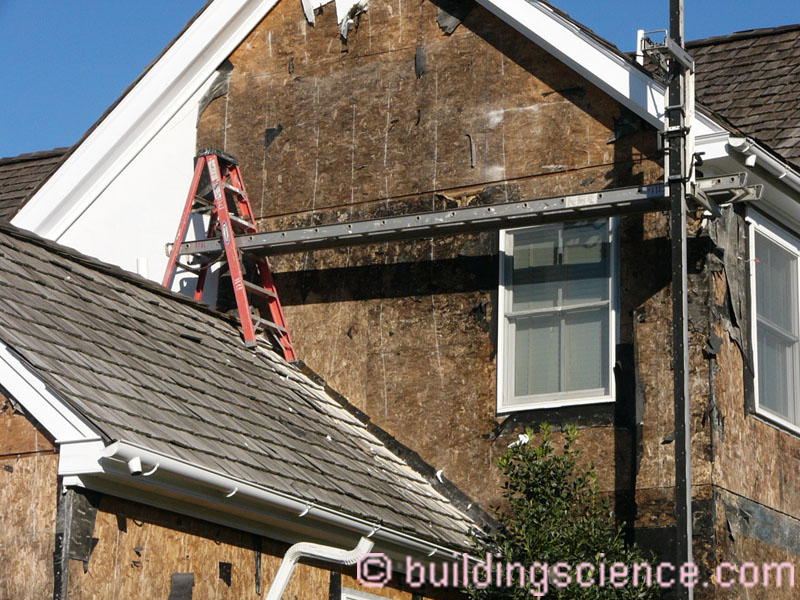
Yeah! Finally! About time! We also have to thank American Society for Testing and Materials (ASTM). Let’s look a little more closely at the code referenced ASTM Standard. Guess what? ASTM E2273 is “Standard Test Method for Determining the Drainage Efficiency of Exterior Insulation and Finish Systems (EIFS) Clad Wall Assemblies”. Guess why we needed a test method for EIFS? Yup, thousands of EIFS buildings with failures (Photograph 3).

Photograph 3: EIFS– There were thousands of EIFS buildings with failures due to the lack of drainage between adhered expanded polystyrene (EPS) rigid insulation and sheathings…both oriented strand board (OSB) and gypsum board. Today, “water managed EIFS” is an excellent system…robust, durable and energy efficient. EIFS went through a “near death” market experience and came roaring back with a high performance product….”hard coat” stucco folks take note…you need to do to stucco what got done to EIFS…drainage, drainage, drainage…
So we actually have to thank failure. Lots and lots of failure. Now, according to “industry observers” the failure “appears to be limited” to stucco and previously to “face-sealed” EIFS….and “particularly to stucco over wood based sheathings”.[3] My comment is: “yes…up to now”. Danger! Danger! Will Robinson![4]
Because of the current large number of failures to stucco over wood based sheathings the model codes are going to be limiting the drainage requirement to stucco assemblies over wood based sheathing….and to regions where it rains more than 20 inches of rain per year (IECC Climate Zones Moist (A) and Marine (C)). This is great as far as it goes.
I respectfully disagree with this limitation. I think drainage should be required in all assemblies except mass walls, curtain walls, storefront glazing systems, precast and concrete tilt up. And with all of the exceptions noted (except mass walls) there needs to be drainage at joints. A modern curtain wall is a marvel of internal drainage. The precast industry pioneered two stage drained joints (Figure 1). And just because stucco is installed over gypsum sheathing it should not be exempted.
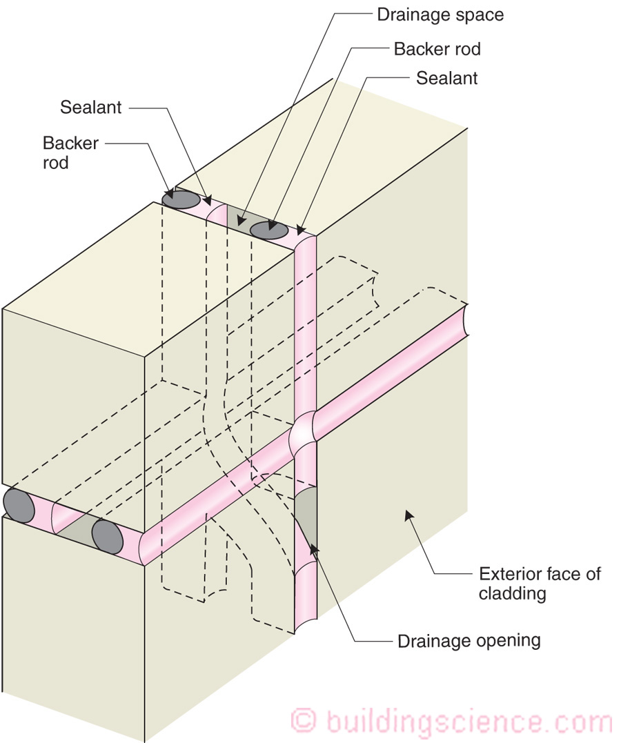
Figure 1: Two-Stage Joint– Precast panel assemblies as well as concrete tilt-up systems employ two-stage joints that facilitate drainage. We have the precast industry for this innovation from the 1950’s and from a legend by the name of Kirby Garden of the Division of Building Research of the National Research Council of Canada.
The argument for a drainage exemption for stucco over gypsum sheathing is that the gypsum sheathing is more vapor permeable (vapor “open”) than wood based sheathings and therefore is able to dry easily and dissipate and redistribute moisture more effectively. Both of these points are correct but….and here is the big but…hydrostatic pressure rules….the wall still will leak and therefore the risk is high….especially in well insulated assemblies that have less available energy for drying.
There is more. There always is. Inward vapor drive and the need for hygric redistribution. And yes, we have been here before (“BSI-061: Inward Drive – Outward Drying”, May 2017and “BSI-038: Mind the Gap, Eh?”, November 2013). You do not need much of a space to provide drainage….but you might need a bigger space to deal with reducing the effects of inward vapor drive (Figure 2) if your water control layer has a high vapor permeance and to allow sheathings that get wet and that are limited in drying inwards (such as oriented strand board (OSB)) to dry outwards (Figure 3).
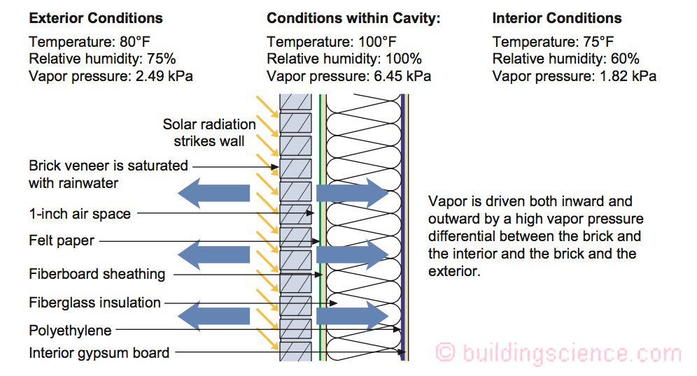
Figure 2: Inward Vapor Drive – With reservoir claddings such as brick veneer, stucco and unpainted wood rain absorbed by claddings can be driven inwards by incident solar radiation. Reservoir claddings behave much like “moisture capacitors”. When the sun hits the “moisture capacitor”, it discharges it. The heating of the stored water raises its vapor pressure. The warm water in the cladding is driven both inward and outward.
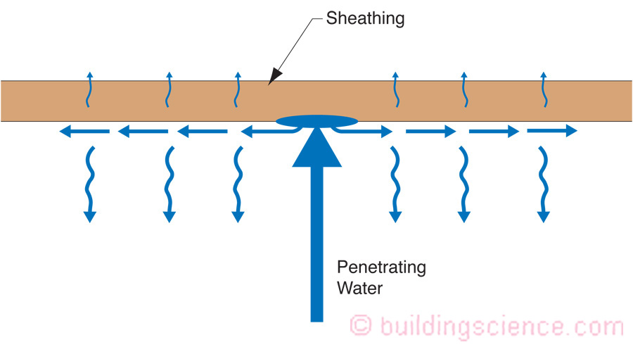
Figure 3: Hygric Redistribution Adjacent the Surface of a Material - Penetrating rainwater hits the sheathing, and is not easily absorbed and is not able to be redistributed within the material or passed inward or outward easily. Redistribution can occur within an air film adjacent the surface of the material when a small air gap is provided. How small a gap? Ah, that’s the rub, eh? Pretty small, so small that “crinkled housewrap has a significant effect, as do small “bumps” or even ribbons of adhesive (think commercial water managed EIFS).
There are two reasonable ways to deal with inward vapor drive – the first is to have a “vapor throttle” and the second is to have an air gap. With a very small air gap (less than 3/16 inch) there is a “sweet spot” (Figure 4) for the vapor transmission control characteristics of water control layers…somewhere between 10 and 20 perms…the “vapor throttle”. Again, yes, we were here before (“BSI-061: Inward Drive – Outward Drying”, May 2017). Now comes the neat part….the larger the air gap the bigger the “sweet spot”….more than 3/16 inch the sweet spot grows to 10 to 30 perms or higher. If you want a higher vapor perm water control layer….you need a bigger gap if you are dealing with reservoir claddings and inward vapor drive. With bigger gaps pretty much everything works vapor transmission wise.
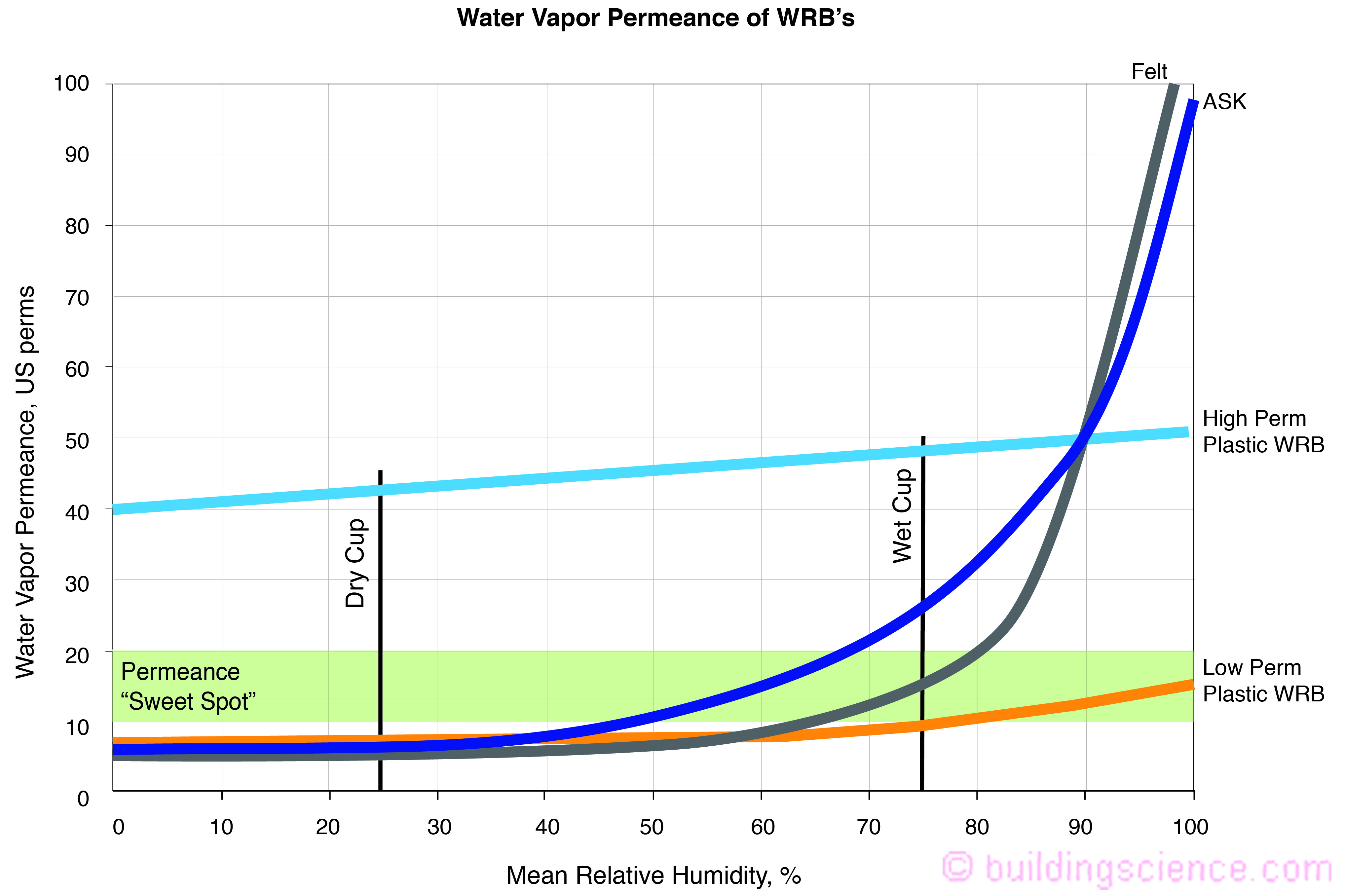
Figure 4: “Sweet Spot” for Vapor Permeance- With a very small air gap (less than 3/16 inch) the “sweet spot” for the permeance of “the layer” is between 10 and 20 perms. Too high and the moisture driven out of the back side of the reservoir cladding into the airspace will blow through the layer and through the gypsum sheathing and into the wall cavity where it can cause problems. Too low, and we reduce the outward drying of the wall cavity through the gypsum board and through “the layer” (wrb) into the airspace during the heating season.
In terms of hygric redistribution a 3/16 inch gap is very conservative…we have seen pretty impressive lateral redistribution in air spaces half as wide[5] under controlled environmental exposure (Photograph 4). Note the previous discussion on high perm water control layers.
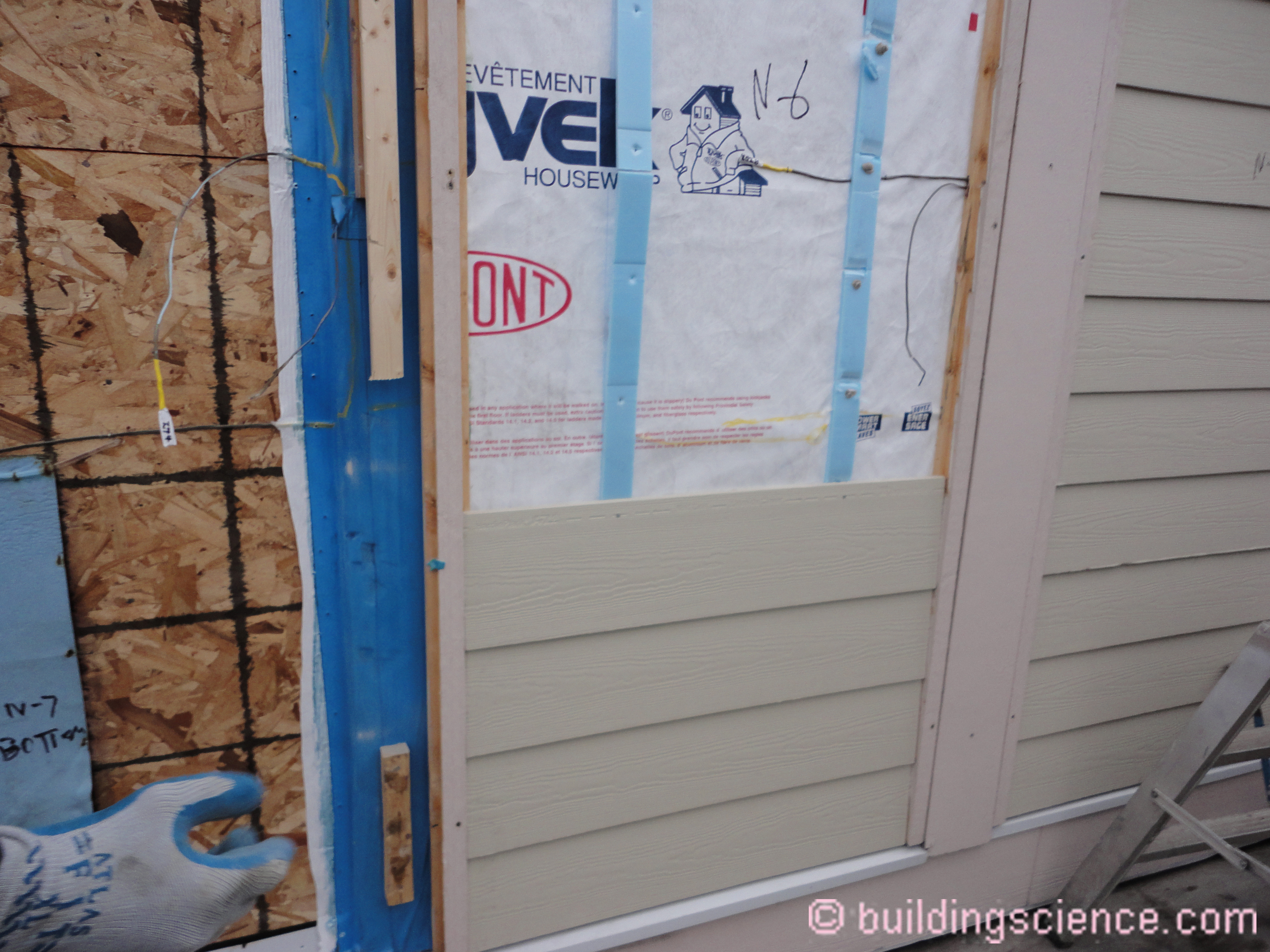
Photograph 4: Hygric Redistribution– Test hut experiment measuring hygric redistribution under various air spaces, cladding types, sheathing types and thermal resistance levels. In this image the air gap is 3/8 inch coupled with fibercement siding, a high perm housewrap and OSB sheathing.
Recall earlier I noted that we now have lots and lots of options because with good drainage pretty much everything works. So what do these options look like?
Most common are “bumpy” housewraps (Photograph 5). The “bumps” create a drainage gap that provide a drainage efficiency of greater than 90 percent, as measured in accordance with ASTM E2273 or Annex A2 of ASTM E2925. The “bumps” also provide for lateral and vertical hygric redistribution.
Photograph 5: “Bumpy” Housewraps - The “bumps” create a drainage gap that provide a drainage efficiency of greater than 90 percent, as measured in accordance with ASTM E2273 or Annex A2 of ASTM E2925. The “bumps” also provide for lateral and vertical hygric redistribution.
We also have 60’s technology…groovy rigid insulations (Photograph 6). Drainage grooves – channels cut into the back of expanded polystyrene (EPS) to provide drainage. This comes to us from New Zealand. Apparently the Kiwis have heard of Vitruvius.
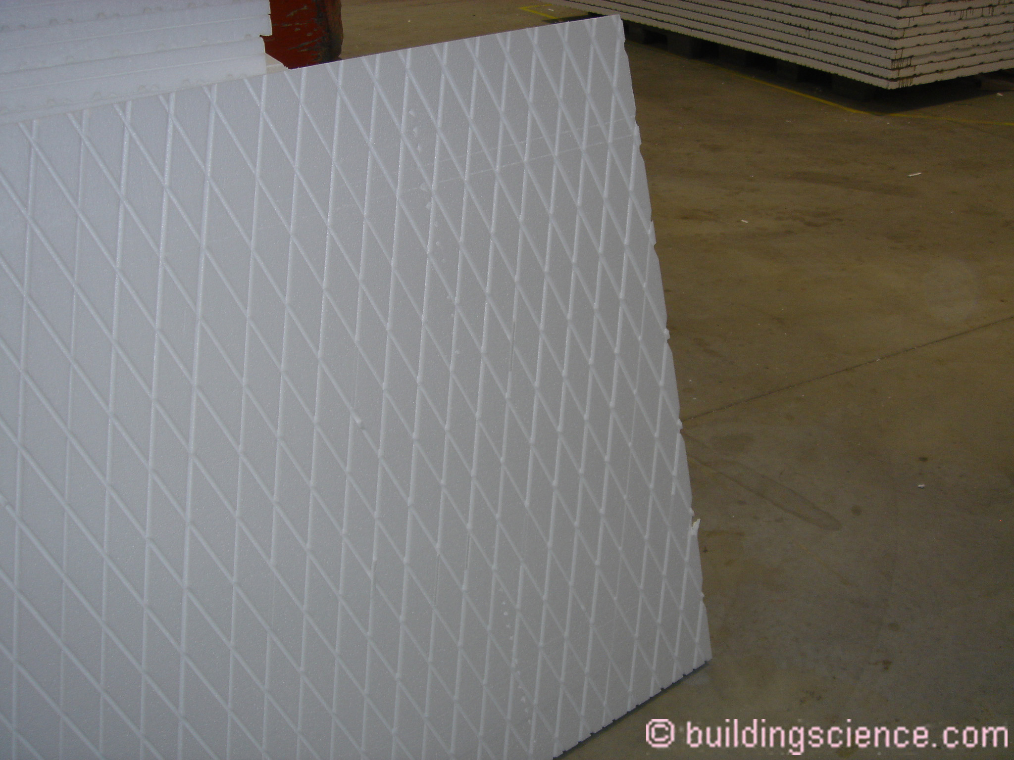
Photograph 6: Drainage Grooves– Channels cut into the back of expanded polystyrene (EPS) to provide drainage. This comes to us from New Zealand. Apparently the Kiwis have heard of Vitruvius.
Drainage can be provided using rigid insulation coupled with filter fabric and channels (Photograph 7). Channels are cut into extruded polystyrene (XPS) coupled with a filter fabric to exclude mortar droppings or to prevent the base coat of stucco from inhibiting drainage.
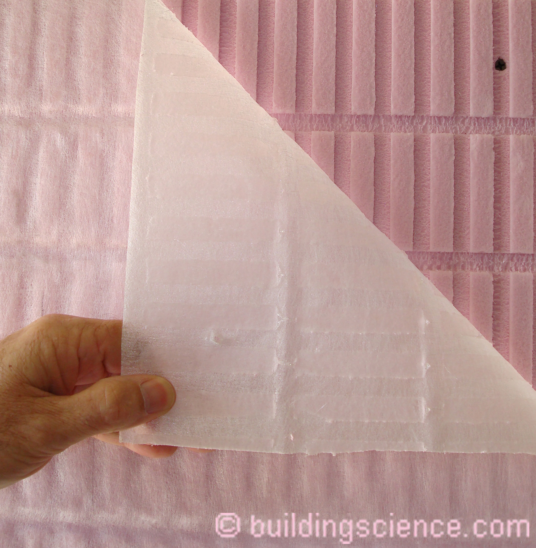
Photograph 7: Filter Fabric and Channels – Channels cut into extruded polystyrene (XPS) coupled with a filter fabric to exclude mortar droppings or to prevent the base coat of stucco from inhibiting drainage.
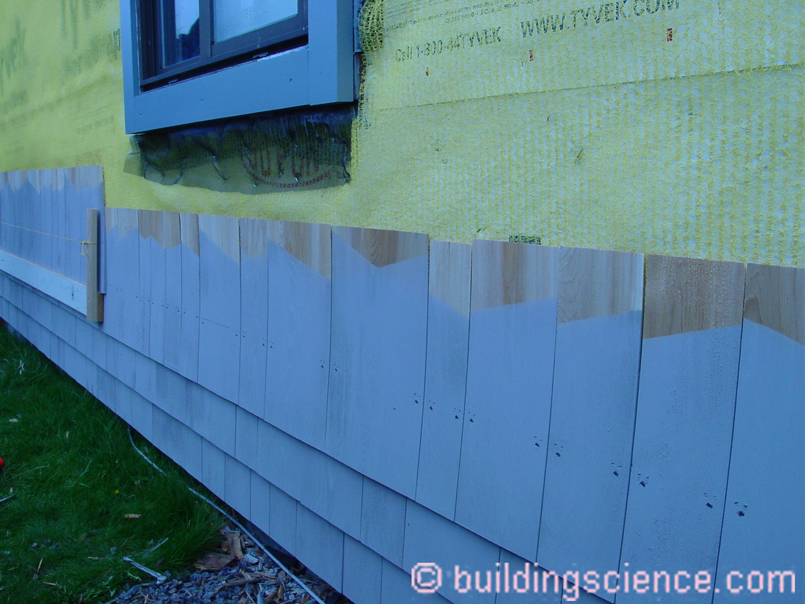
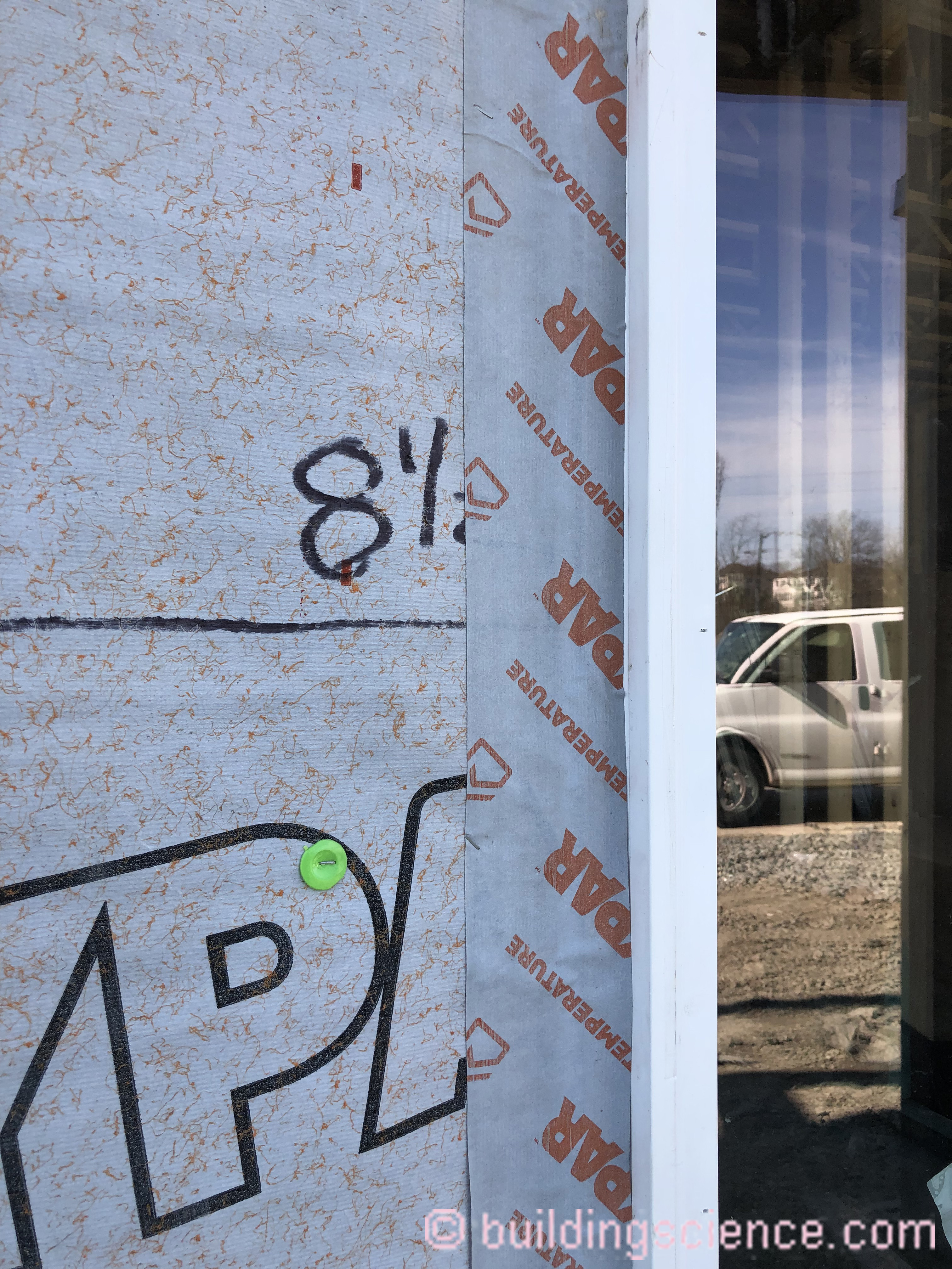
In high rainfall zones and large buildings drainage and hygric redistribution for stucco assemblies are typically provided by a drainage mat installed over a mechanically attached WRB installed over exterior gypsum sheathing (Photograph 8).
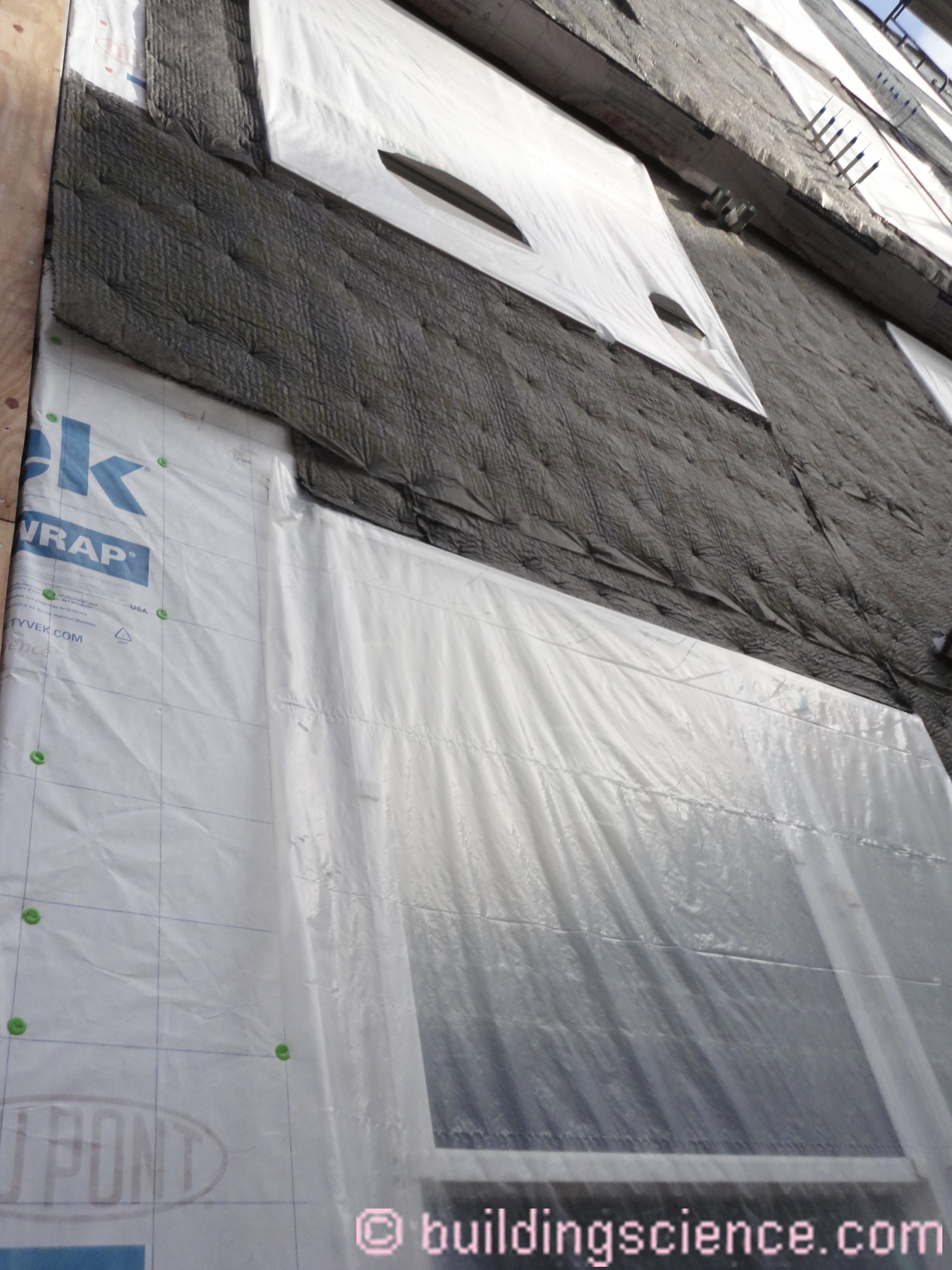
Photograph 8: Drainage Mat– Drainage and hygric redistribution for a stucco assembly is provided by a drainage mat installed over a mechanically attached WRB installed over exterior gypsum sheathing.
So with a good drainage matric I don’t think we need much of a material metric for water control layers….Type I, or Type II – ASTM E2556 Standard Specification for Vapor Permeable Flexible Sheet Water-Resistive Barriers Intended for Mechanical Attachment…or No 15 felt complying with Type I ASTM D226 Standard Specification for Asphalt-Saturated Organic Felt Used in Roofing and Waterproofing…or a fluid applied WRB…or sheet goods with integral water control layers…whatever, they all work…with drainage. The goal should be to get rid of the crazy metrics that restrict materials and innovative approaches…if you have good drainage. With good drainage…following the proposed code metric…pretty much everything works.
By George, I think we’ve got it…
* My wife and I love musicals. When we were dating in early 1990 one evening we were both watching My Fair Lady. Just after Eliza Doolittle says “The rain in Spain stays mainly in the plain” I blurted out “You need to drain the rain on the plane” and the term “drainage plane” was born. Yes, alcohol was involved. The next day I was lecturing on rain control and I got the class of builders and architects to chant “you need to drain the rain on the plane”. I pointed out that the rain draining on the “drainage plane” needed to be directed to a flashing….and that lead to the next spur of the moment chant “if you want to save cash, flash…” followed by “don’t be a dope, slope”. I have been milking these lines now for almost 30 years…I am more than somewhat bemused that codes and manufacturer’s literature today refer to “drainage planes”…if they only knew.
[2] De architectura, Marcus Vitruvius Pollio, around 25 BC and yes, we were here before (“BSI-086: Vitruvius Does Veneers”, May 2015).
[3] Overheard during testimony at the “Committee Hearings” in Albuquerque for proposed building code changes for the 2021 IBC and the 2021 IRC. Weasel words at their best. Sounds like 1995 to 2000 all over again during the “face-sealed EIFS denial stage”.
[4] Quote from Robot B9 and the science-fiction television series Lost in Space. It was not from Robby the Robot of “Forbidden Planet” fame…..although Robby the Robot did actually make guest appearances in two Lost in Space episodes.
[5] The “Vancouver test hut” decade long experiment…. “BSI-058: Parthenon, Eh!”, March 2012.