A multi-zone, single-gas, tracer gas decay measurement technique was used to test the ventilation systems of a single-story, slab-on-grade 1350 sq. ft. house in Las Vegas, Nevada, and a two-story, 3192 sq. ft. house with basement in Minneapolis, Minnesota. Some of the systems were independent of the central air distribution system, while others were integrated with it. In general, results showed that all ventilation systems benefitted from periodic operation of the central fan, giving excellent uniformity of ventilation air distribution. System without central fan recirculation showed poor ventilation air distribution for closed rooms where there was no ventilation system duct. This article was first published in ASHRAE Transactions 2000, Vol. 106, Part 2. Reprinted with permission.
Introduction
Supply ventilation systems draw outside air from a known location and deliver it to the interior living space. This known location should be selected to maximize the ventilation air quality. The ventilation air can be treated before distribution to the living space (i.e., one or more of being heated, cooled, dehumidified, filtered, cleaned). If supply ventilation air is not preconditioned, it should be mixed with recirculated indoor air to mitigate discomfort effects of the outside air and prevent condensation. In cold climates, to prevent condensation on ventilation supply registers, the mixing ratio should be a minimum of two parts inside air with one part outside air, based on -10°F outdoor dry-bulb temperature, 68°F indoor dry-bulb temperature, and 42°F indoor dew-point temperature. Supply ventilation will tend to pressurize an interior space relative to the outdoors, causing inside air to be forced out through leakage openings located randomly throughout the building envelope. This strategy is advantageous in warm-humid climates to minimize moisture entry into the building structure from outdoors.
Exhaust ventilation systems expel inside air to the outdoors, tending to depressurize an interior space relative to the outdoors, inducing infiltration. This strategy can be advantageous in climates with cold winters but should not be used in hot-humid climates. In mechanically cooled buildings in hot-humid climates, if interior negative pressure causes moisture-laden outdoor air to enter the building envelope, moisture can condense on cool surfaces, and, if restricted from drying to the inside, problems of material durability and indoor air quality can result. Exhaust ventilation systems in all climatic zones draw outside air from leakage openings and pathways located randomly throughout the building envelope; thus, it is not possible to treat the outside air before it enters the living space. The "ventilation" air could be fresh and healthy or it could be coming from locations with high pollutant concentrations. For example, ventilation air drawn from a garage, crawl space, basement sump, or from underneath a concrete slab may induce entry of fuel vapors, combustion gases, insecticides, radon gas, excessive water vapor, and fungal or mold spores.
Balanced ventilation systems exhaust inside air to the outdoors and supply outside air to indoors. Balanced ventilation, by definition, should not affect the pressure of an interior space relative to the outdoors, although in reality there may never be a true balance due to pressure fluctuations from wind, buoyancy forces (stack effect), and air conveyance system forces. This ventilation strategy can be used effectively in any climate. It is possible to filter or condition the ventilation air before it enters the living space.
Ventilation systems can be powered and ducted in many different ways. How the system is powered will affect both first cost and operating cost. How the system is ducted will affect first cost and the ability of the system to distribute ventilation air uniformly to all occupied spaces. For example, ventilation systems that utilize an existing central heating and cooling system’s air-handler unit fan and ducts have low additional first cost and provide excellent ventilation air distribution but have relatively higher operating cost. Systems that utilize smaller, separate fans and ducts, and achieve comparable whole-house ventilation air distribution, have a relatively high first cost but lower operating cost. Table 1 shows a general matrix of the advantages and disadvantages of various generic ventilation systems. The term “fully ducted” denotes ducts extending from the air conveyance device to all bedrooms, to other habitable conditioned rooms with doors, and to the common areas. A ventilation system that was not fully ducted would be one where habitable and conditioned rooms were isolated from the ventilation system.
Table 1: Matrix of Advantages and Disadvantages of Ventilation Systems

Because of the many ventilation system configurations available, and because of the significant differences in cost and performance, choosing between ventilation systems can be a complex task. Field testing was performed to help quantify performance characteristics to develop guidelines related to cost and performance.
The focus of this study was to evaluate the effectiveness of different ventilation systems in providing design ventilation rates and uniform distribution of ventilation air.
Test Setup and Initial Measurements
Las Vegas, Nevada
Two ventilation systems were installed in the same 1350 ft2 house, in Las Vegas, Nevada, to individually evaluate their effectiveness in providing adequate air change rates and uniform distribution of outside air throughout the house. The house was a three-bedroom, two-bath, one-story wood frame with slab-on-grade foundation and attached two-car garage. The entire air distribution system for the central heating and cooling system was inside the conditioned space, within the thermal and air boundary of the unvented, “cathedralized” attic, wherein the insulation is installed directly below the roof sheathing instead of above the ceiling gypsum board (Rudd and Lstiburek 1998). This configuration eliminates air distribution system losses to the outside. To ensure adequate air distribution within the building envelope, total duct leakage should be limited to 10% of the system flow.
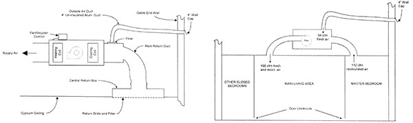
Figure 1 (above left): Schematic of central-fan-integrated supply ventilation as installed in the house tested; Figure 2 (above right): Schematic of the separate supply ventilation system installed in the house tested
The first ventilation system tested was central-fan-integrated supply ventilation (Rudd 1998), wherein outside air was ducted from a high wall location on the building exterior to the return air side of the central heating and cooling system fan. This system utilized the existing central heating and cooling system’s ducts and fan, located inside conditioned space, to distribute ventilation air and conditioned air at the same time. A fan recycling control (ACH&R News 1998; Builder 1998; EDU 1997, 2000) was used to cycle the central fan periodically to distribute ventilation air and provide whole-house mixing during periods when the central fan was inactive (i.e., no thermostat demand for heating or cooling). A schematic of the central-fan-integrated supply ventilation system installed in the test house is shown in Figure 1. The outside air duct was a four-inch-diameter expanded aluminum duct connected to a four-inch wall cap at the exterior wall and connected to the return plenum of the central heating and cooling air-handler unit through a transition box that held a standard 12-by-12-in. furnace filter. The outside air duct installed in this house was undersized according to the original design, allowing only 47 ft3/min through the four-inch duct. The target outside airflow for this house was 80 ft3/min, calculated by Equation 1 (Rudd 1998) and the following given parameters:
- 40 ft3/min continuous ventilation required for the occupants of the three-bedroom house
- 33% central fan duty cycle
- 0.10 air changes per hour in between central fan cycles
- house volume of 12,150 ft3 . . .
Download complete document here.