Exterior insulation retrofit is a reasonable step if a recladding of the building is already being done for aesthetic or ongoing maintenance reasons. This paper presents many of the lessons learned from superinsulation retrofit experiences, including overall enclosure strategies, such as air barriers, drainage planes, and moisture control. Several case-specific solutions to particular problems are described, including exterior air barrier approaches, wall sill replacement, and several approaches dealing with window penetrations. In addition, detailing recommendations and economic analysis of these measures are presented. Hygrothermal simulations were run to evaluate the changes in sensitivity to moisture intrusion due to these retrofit measures.
Introduction
The issues of climate change, energy security, and economics are all strong drivers for improving energy efficiency levels in a variety of sectors. The residential and commercial building sectors consumed roughly 40% of the primary energy used in the United States in 2008; this can be further subdivided into the residential (21%) and commercial (18%) sectors (DOE/EIA 2009). In residential construction, although some inroads have been made in new houses, the stock of existing housing represents a huge opportunity for energy retrofits. For instance, Gitt (2009) notes that of the existing stock of 120 million housing units, 70% of them were built before any energy codes were enacted. Although the effectiveness or ineffectiveness of various energy codes can be debated, it is reasonable to assume a general trend of increasing energy efficiency with the presence of (and/or more stringent) energy codes.
The nationwide distribution of housing stock by geographic census region and age is shown in Figure 1, based on US Energy Information Administration (EIA 2005) data. It demonstrates trends noted by others (Lutz 2004): for instance, much of the oldest housing stock is concentrated in the Northeast, and since the 1970s, the majority of new construction was concentrated in the South and West regions.

Figure 1: Vintage of US housing units, subdivided by US census region (EIA 2005)
Given the body of older, less-efficient housing stock, it appears that there is substantial "low-hanging fruit" for energy efficiency retrofits in existing housing. The current political climate is conducive to the implementation of home energy efficiency improvements, both on state and federal levels. However, energy retrofits have historically proven to be difficult to implement in quantity, due to "regulatory constraints, high costs, and the complexities of reaching a fragmented market" (Gitt 2009). Existing homes are a particular challenge because of the variety of building types, characteristics, site-walls are sensitive to wintertime outward moisture movement from interior sources, either by vapor flow or airflow, with the latter being of greater importance. As a result, to ensure durability, these walls depend upon the workmanship of the air barrier and (to a lesser extent) the vapor barrier. The cold temperature of the exterior wall sheathing (due to the insulation levels/reduction in heat flux) results in substantial periods when there is wintertime condensation risk at that surface. In contrast, the retrofit described here places roughly 2/3 of the thermal resistance outboard of the condensing surface (interior face of the existing sheathing boards). This raises the wintertime condensing surface temperature, and substantially reduces the risk of interstitial condensation. Therefore, the assembly described here has some notable durability advantages. In addition, this assembly addresses thermal bridging at the rim joist, which is often a weakness in double stud walls.
In terms of airflow control, it is recommended that the primary air barrier in a cold climate be located on the interior, to avoid exfiltration of moisture-laden air and resulting interstitial condensation (Lstiburek 2006). In an exterior retrofit, however, the air barrier is typically retrofitted outboard of the existing structure, which raises some durability questions. In this case, though, the air barrier is located 1/3 of the way through the thickness of the assembly (from the interior): again, the high insulation value outboard of the air barrier greatly reduces the condensation risks of this assembly. One final question revolves around the choice of an exterior retrofit, as opposed to an interior (“gut”) retrofit. Insulating wall assemblies beyond cavity fill levels requires the disruption of either the interior or exterior fabric; the choice is a value judgment that must be made on a case-by-case basis.
One of these surfaces may have greater or less aesthetic or historical significance. However, there are some arguments to be made for an exterior retrofit. For one, the interior is still habitable during this retrofit; in fact, two of the following case studies were conducted on occupied houses. Increasing the thickness of the wall at the interior results in a loss of habitable square footage. In exterior retrofits where the existing cladding is first removed, it provides an opportunity to inspect the condition of the building, including finding and repairing previously undetected leakage or moisture damage. More limited insulation techniques might not find these issues, resulting in long-term moisture damage consequences, which would be exacerbated by the reduction in heat flow (and thus drying potential) due to insulation retrofits. The exterior insulation technique described here places non-moisture-sensitive insulation outboard of the existing structure, thus providing a layer of protection.
Finally, applying insulation on the exterior can successfully handle details such as stairwells on exterior walls and intersecting tee walls, which have limited options when insulating from the interior.
Previous Work
The authors do not mean to imply that the use of substantial amounts of thermal insulation outboard of the structure is an innovative technique by any means; this method has a long history in the building science community. The basic concepts were spelled out by Hutcheon (1964); this method involves the use of a vapor-, air-, and water-control layer exterior to the structure (e.g., bituminous adhered membrane), with insulation outboard of this layer, and the finish cladding exterior to the insulation. These concepts were also described by Lstiburek (2007); some implementations have included the pressureequalized rain screen insulated structure technique (PERSIST) construction method (Baker and Makepeace 2001), residential exterior membrane outside insulation technique (REMOTE) by the Cold Climate Housing Research Center (Benesh 2009), and the Building America/Hydaburg Tribe house (Lstiburek 2009). The challenges associated with exterior insulation, such as cladding attachment through thick nonstructural insulation, and the attachment of nonconditioned portions of the outer shell (e.g., decks and porch roofs) were also encountered in the projects described here. However, it should be noted that the techniques used in these projects are not completely analogous to this previous work.
The exterior insulation concept is not limited to new construction; some similar techniques were applied in a retrofit situation by Orr and Dumont (1987), in their so-called “chainsaw retrofit.” This project was the exterior insulation retrofit of a circa 1970 stucco-clad bungalow; one key point was that the entire exterior enclosure was wrapped with a 6 mil (0.15 mm) polyethylene vapor and air barrier. In order to avoid wrapping the overhanging roof eave, the entire detail was cut off flush (thus the “chainsaw retrofit” name), rendering the shape of the house a relatively simple solid with planar faces. An exterior wood frame was constructed outboard of the walls and roof, fiberglass insulation was applied in the cavity formed by the frame, and exterior sheathing and cladding were applied. High levels of exterior insulation were installed: R-39 (RSI 6.8) roof, and R-40 (RSI 7.0) walls. The researchers measured a substantial increase in airtightness, going from 2.95 ACH 50 (air changes per hour at 50 Pa test pressure) to 0.29 ACH 50. Measured results indicated a substantial reduction in heating load (factor of 2.4 reduction).
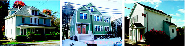
Figure 2: Front views of case study houses (left to right): Concord Four Square, Arlington Duplex, and Bedford Farmhouse
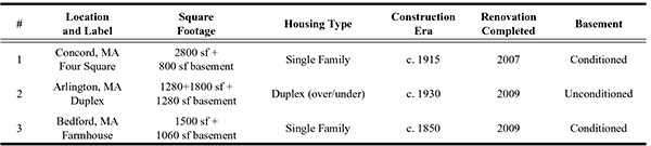
Table 1: Summary of Case Study Characteristics
Researchers at Oak Ridge National Laboratory (Stovall et al. 2007) examined some exterior wall insulation and airtightness retrofit options. They first took laboratory thermal performance (“hot box”) measurements of heat flow reductions in test walls (both opaque wall only, and with an installed window). The wall upgrades included options commonly used in retrofit residing, including 3/8 in. (9.5 mm) and 1/2 in. (12 mm) extruded polystyrene (XPS) foam, 1 in. (25 mm) of foil-faced polyisocyanurate, and expanded polystyrene (EPS) contoured to fit the profile of hollow vinyl siding. The researchers also performed laboratory measurements of the air leakage characteristics of several window-to-wall air sealing methods. They combined this information with whole-house energy simulations, to estimate energy savings associated with these retrofits for three house models in ten climate zones. The predicted heating and cooling energy cost savings showed expected patterns of greater savings with increasing R-value; for reference, the 1 in. (25 mm) foil-faced polyisocyanurate showed typical savings in the 10–15% range when applied over an existing insulated frame wall. It is interesting to note that these levels of savings were even seen in cities typically associated with greater cooling loads, such as Phoenix, AZ, Atlanta, GA, and Bakersfield, CA. The one exception was Miami, FL, which only showed 5% savings with the described assembly. Of course, it must be remember that although many cities showed the same percentage (10–15%) savings, the absolute magnitude of savings (and thus associated energy paybacks) will vary with local heating and cooling loads. . .
Download complete document here.