A little bit of history…back in the day the United States was known for its manufacturing prowess[1]. In high speed and high volume production “punching[2]” was and is the least expensive method of creating holes in sheet goods. In “punching” a “tool” called a “punch” is forced through a sheet creating a hole by shearing. A “die” on the opposite side of the sheet supports the material around the perimeter of the hole providing a clean edge[3].
Windows and doors are “holes” in the “sheet-like walls” of buildings. Hence the term “punched openings”. Too often window and door openings are a “sucker punch” to contractors and engineers…an unexpected without warning…failure in water management….Yup, bad pun…intended.
The basic concept for dealing with punched openings is straightforward:
• Connect the water control layer of the wall to the water control layer of the window or door.
• Connect the air control layer of the wall to the air control layer of the window or door.
• Connect the vapor control layer of the wall to the vapor control layer of the window or door.
• Connect the thermal control layer of the wall to the thermal control layer of the window or door.
• Install the window or door plumb, level and square.
• Don’t let the wind suck or push the window or door out of the wall.
• Done.
So how come it gets so complicated? Well, not all walls are alike. Not all windows and doors are alike. Not all water and air control layers are alike.
In most building enclosures designed and constructed today the water and air control layers are on the outside of the structure and often combined. There are good reasons for this. We have been here before (“Forty Years of Air Barriers”, ASHRAE Journal, March 2015). Sometimes the water and air control layers are installed directly over the “sheathing” or are sometimes integral with the sheathing…they are the sheathing. This part is the “straightforward” part. The walls are easy. The issue is connecting the windows and doors to the walls…specifically to these layers in the walls.
We have both flanged and unflanged windows and flanged and unflanged doors. For the record, it is a lot easier to install flanged windows and doors than unflanged windows and doors. So much so that there are kits marketed and sold that add flanges to unflanged windows and doors. And we have been here before addressing flanged assemblies (“Windows Can Be A Pain”, ASHRAE Journal, April 2015).
Flanged windows and flanged doors have almost exclusively been limited to residential construction whereas unflanged windows and doors are commercial and institutional stalwarts. A bit of history explains why.
Commercial and institutional buildings were, until recently, masonry mass construction and residential construction has been by and large wood frame.
Masonry mass wall construction required through-wall flashing at punched openings – the flashing had to extend from the interior lining all the way to the exterior face of the cladding. Whereas with wood frame construction the flashing only needed to integrate with the building paper layer behind the cladding. Masonry walls for almost a century were typically a brick veneer over a block back-up wall with a 2-inch cavity in between. Here is the key point. Both the brick layer and the block back-up were laid simultaneously. No scaffolding was needed…everything was done from the “inside”. With both layers going up at the same time it was not possible to install a water control layer on the exterior of the block back-up wall (Figure 1). It would have been bad practice to deliberately “drain” into the air gap between the two layers. Penetrating rainwater typically ran down the back face of the brick layer not on the outer face of the block back-up wall. Through-wall flashing was typically located at the bottom of the walls.
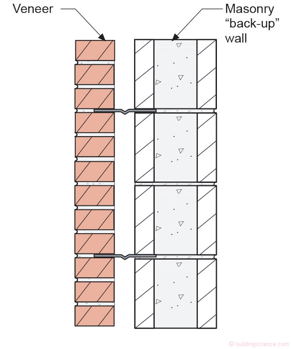
Figure 1: Masonry Mass Wall– Traditionally there was no water control layer applied to the exterior of the masonry “back-up” wall. Hence through-wall flashing was necessary at punched openings to drain the openings to the exterior face of the veneer. It was a bad idea to drain the openings into the cavity airspace. The use of through-wall flashings made it impractical to used flanged windows and doors at punched openings.
Since there was no water control layer applied to the exterior of the masonry “back-up” wall through-wall flashings were also necessary at punched openings to drain the openings to the exterior face of the veneer. Note that it was a bad idea to drain the openings into the cavity airspace. The result of this necessary use of through-wall flashings made it impractical to use flanged windows and doors at punched openings.
In residential frame construction, building papers were common on the exterior of sheathings – between the sheathings and claddings. Because of this it was not necessary to drain the punched openings to the face of the claddings or veneers. The punched openings could be drained to the exterior face of the building papers. Flashings were dramatically simplified as a result in residential construction compared to those in commercial and institutional buildings - and ultimately integrated with the windows and doors themselves. Flanged windows and doors became common.
Today, in commercial and institutional construction, we typically use frame construction – steel studs and gypsum sheathing are common – and we have water and air control layers installed directly over the sheathings or integral with the sheathings as in residential construction. Where we have masonry “back-up” walls we almost always install water and air control layers directly to the exterior face of the masonry “back-up” wall. As such it is not necessary to drain the punched openings to the exterior face of the claddings or veneers and it is possible to use flanged windows and doors. Things can be simplified. Flanges should rule. Alas, it is not so. Tradition still rules and will likely continue to do so for the foreseeable future. Unflanged windows and doors will continue to be stalwart in commercial and institutional construction.
So how do we make things work with unflanged windows and doors? We use the same fundamental approach that is used with flanged windows and doors. Drainage and “two-stage” joints (Figure 2). The same physics apply. Again, we have been here before (“High Risk Walls”, ASHRAE Journal, July 2011 and “A Cup in The Rain”, ASHRAE Journal, April 2008).

Figure 2: Two-Stage Joint– An inner and outer seal with drainage between the two seals. Came to us from the precast industry in the 1960’s and the legendary Kirby Garden (Canadian Building Digest 40 – Rain Penetration and its Control, April 1963).
We are going to do a series of 5 different “punched openings.” We are going to limit ourselves to only window openings with unflanged windows. But we are going to look at fluid-applied water and air control layers, mechanically-attached water and air control layers, fluid-applied “rough opening” flashing linings, self-adhered membrane rough opening flashing linings and continuous insulation with both “innie” and “outie” windows. All the claddings are back ventilated and drained. Let me repeat. All the claddings are back ventilated and drained. Phew!
First up, a fluid-applied water and air control layer coupled with a fluid-applied flashing extending into the “rough opening” (Figure 3a, Figure 3b and Figure 3c). The exterior sheathing is typically exterior gypsum board but can also be oriented strand board (OSB) or plywood. A fluid-applied membrane “flashing” is used to line the entire perimeter of the rough opening extending from the interior of the rough opening framing to the exterior face of the exterior sheathing wrapping around the exterior opening edge and extending 4 to 6 inches over the face of the exterior sheathing. I call this process “raccooning”…like the black outline around the perimeter of the eyes of a raccoon. Note the exterior and interior sealant joints. Do not confuse the exterior sealant joint with the “cladding termination seal.” The outermost “seal” is an aesthetic joint…sometimes called the “beauty bead”[4]. Also note that the exterior sealant joint is weeped at the bottom of the window opening. And note the back dam. There should always be a back dam. Let me repeat…there should always be a back dam. And finally, note that there is a difference at the head of the window opening between the “head flashing” and the “drip edge cladding trim”. One provides a critical function from a water management perspective and the other is typically aesthetic providing closure to the bottom of the cladding system.
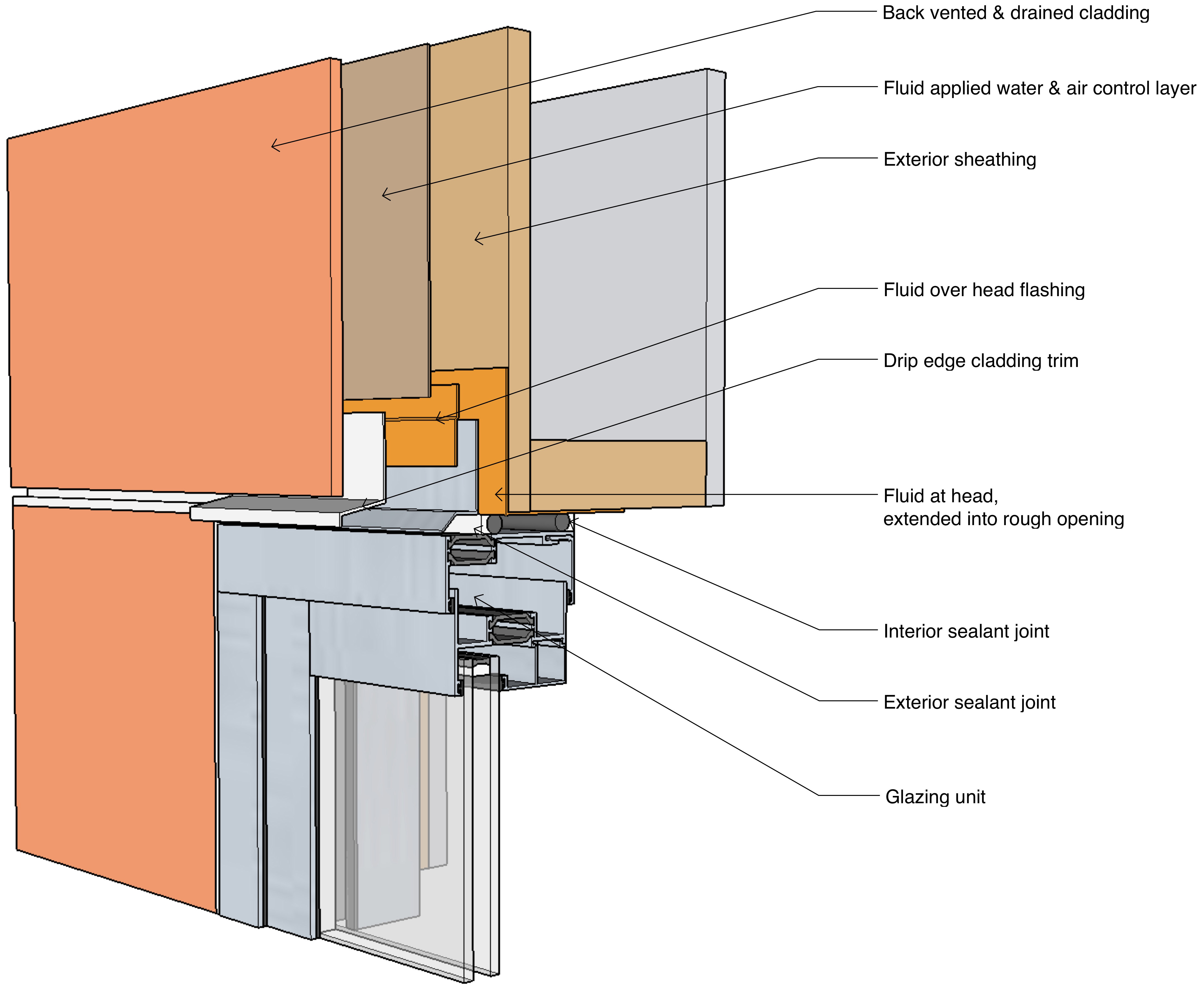
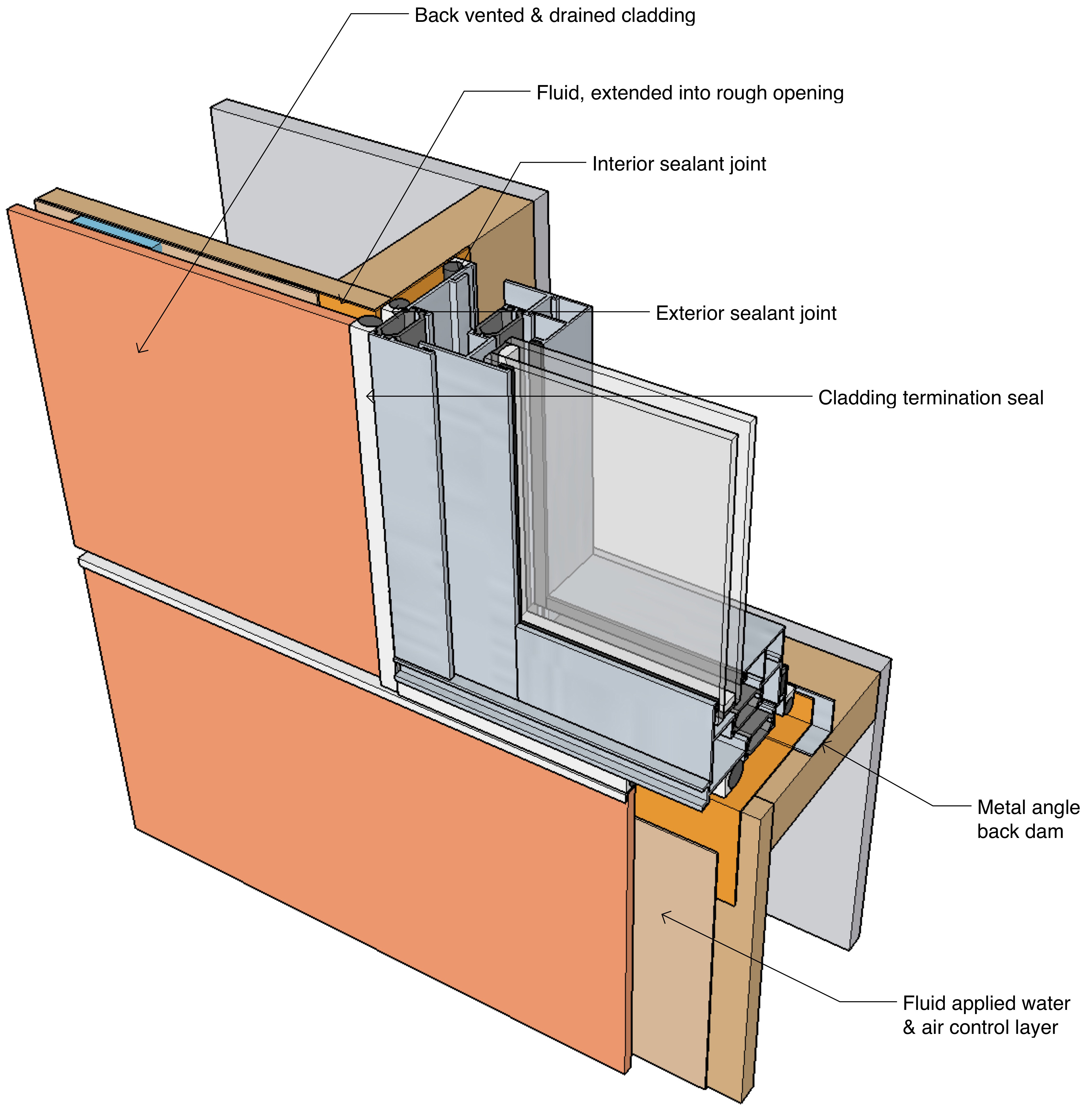
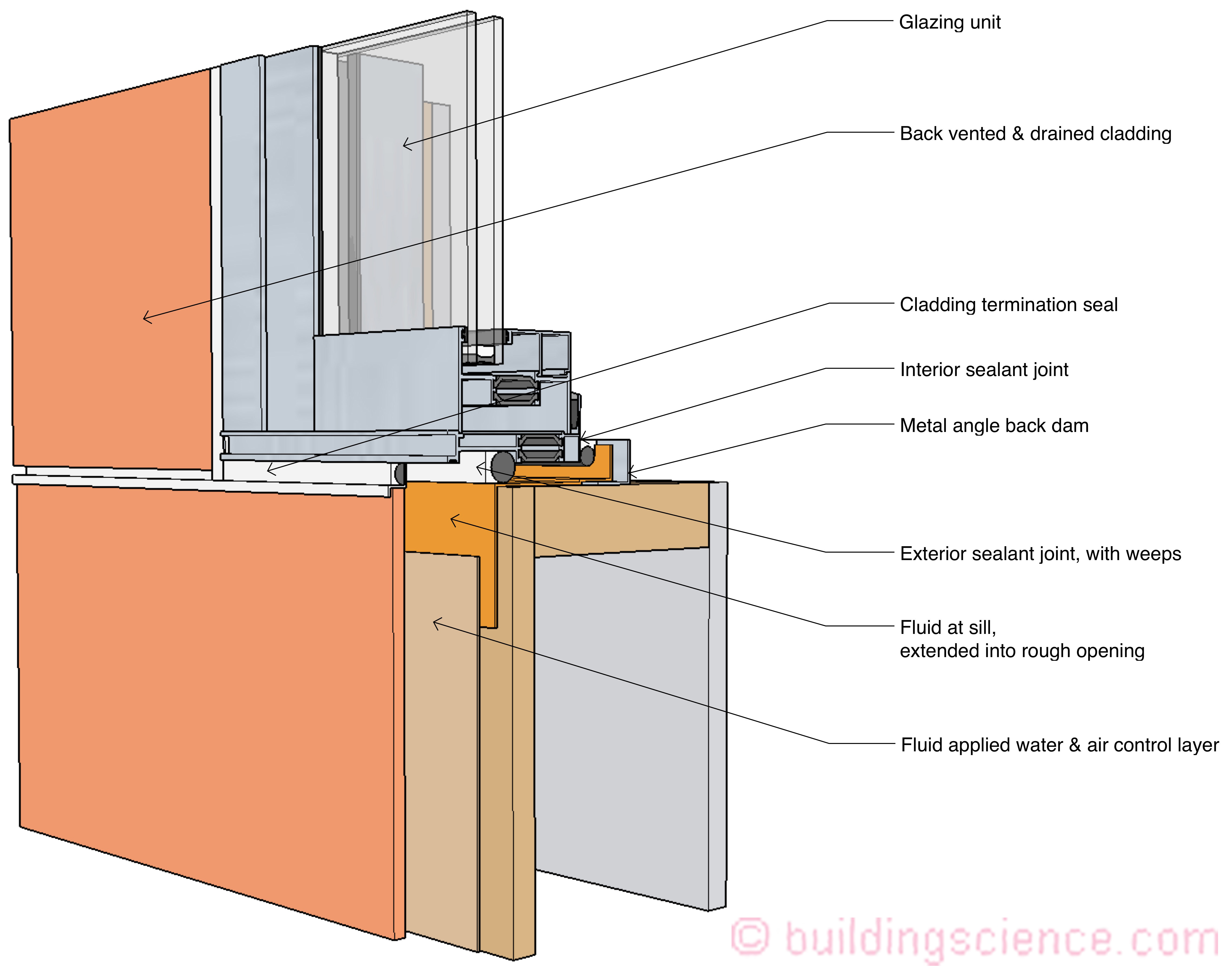
Figure 3a, 3b and 3c: Fluid-Applied Water and Air Control Layer Coupled with a Fluid-Applied Flashing- A fluid-applied membrane “flashing” is used to line the entire perimeter of the rough opening extending from the interior of the rough opening framing to the exterior face of the exterior sheathing wrapping around the exterior opening edge and extending 4 to 6 inches over the face of the exterior sheathing. Note the exterior and interior sealant joints. Do not confuse the exterior sealant joint with the “cladding termination seal.” Also note that the exterior sealant joint is weeped at the bottom of the window opening. And note the back dam.
Next up, a mechanically-attached water and air control layer coupled with a fluid-applied flashing extending into the “rough opening” (Figure 4a, Figure 4b and Figure 4c). Note the fluid seal over the head flashing connecting to the “raccooned” fluid-applied flashing extending upward over the exterior sheathing. The fluid seal could also be replaced with a membrane flashing tape. Also note that the mechanically-attached water and air control layer extends over the top of head flashing and seal. This mechanically-attached water and air control layer should not be sealed at its bottom edge at the head of the window to allow incidental water that penetrates the mechanically attached water and air control layer to drain out at the head (we have been here before…see “Stuck on You”, ASHRAE Journal, February 2013). Finally, note the “shingling” of the “taped” mechanically-attached water and air control layer at the sill.
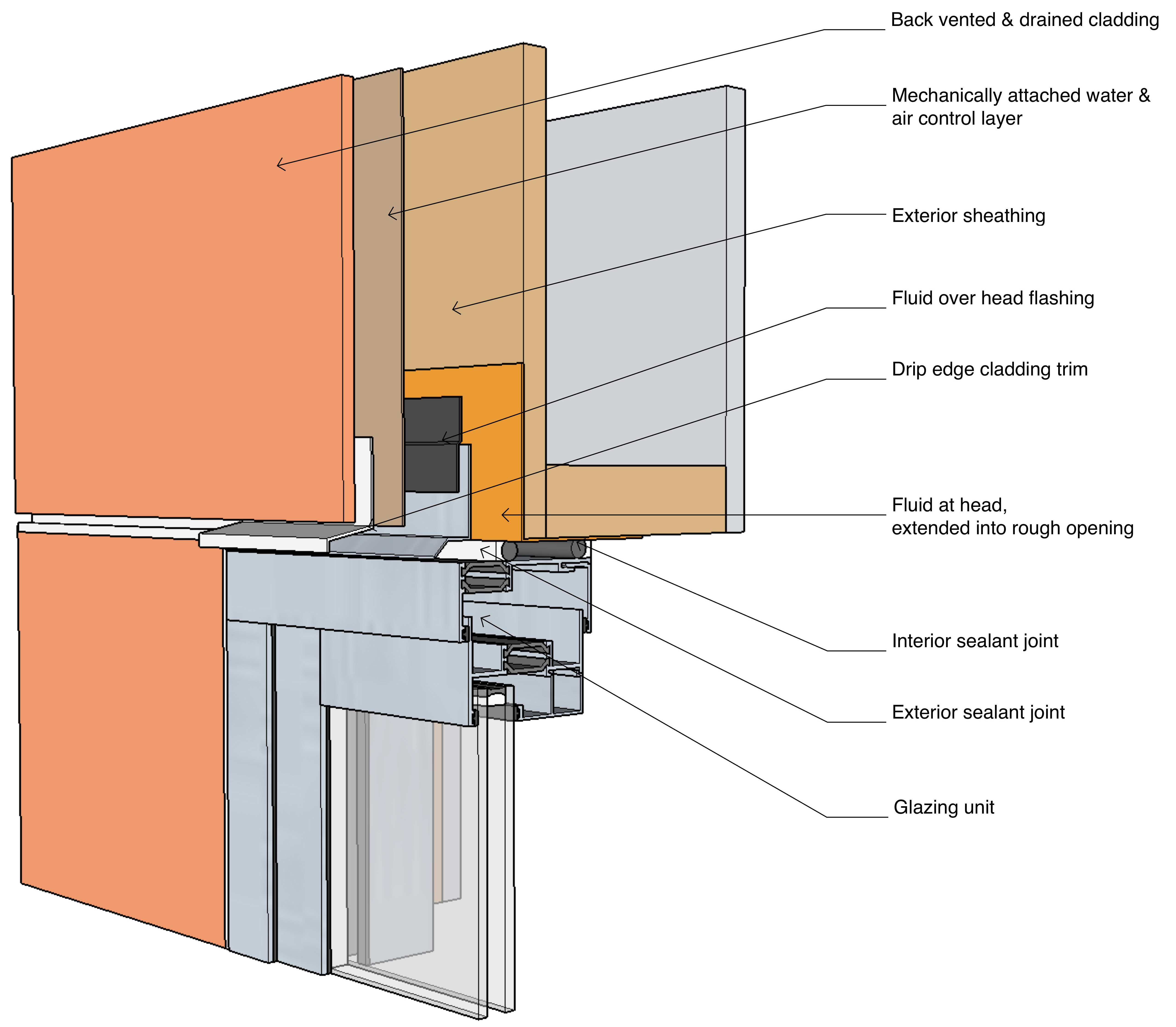
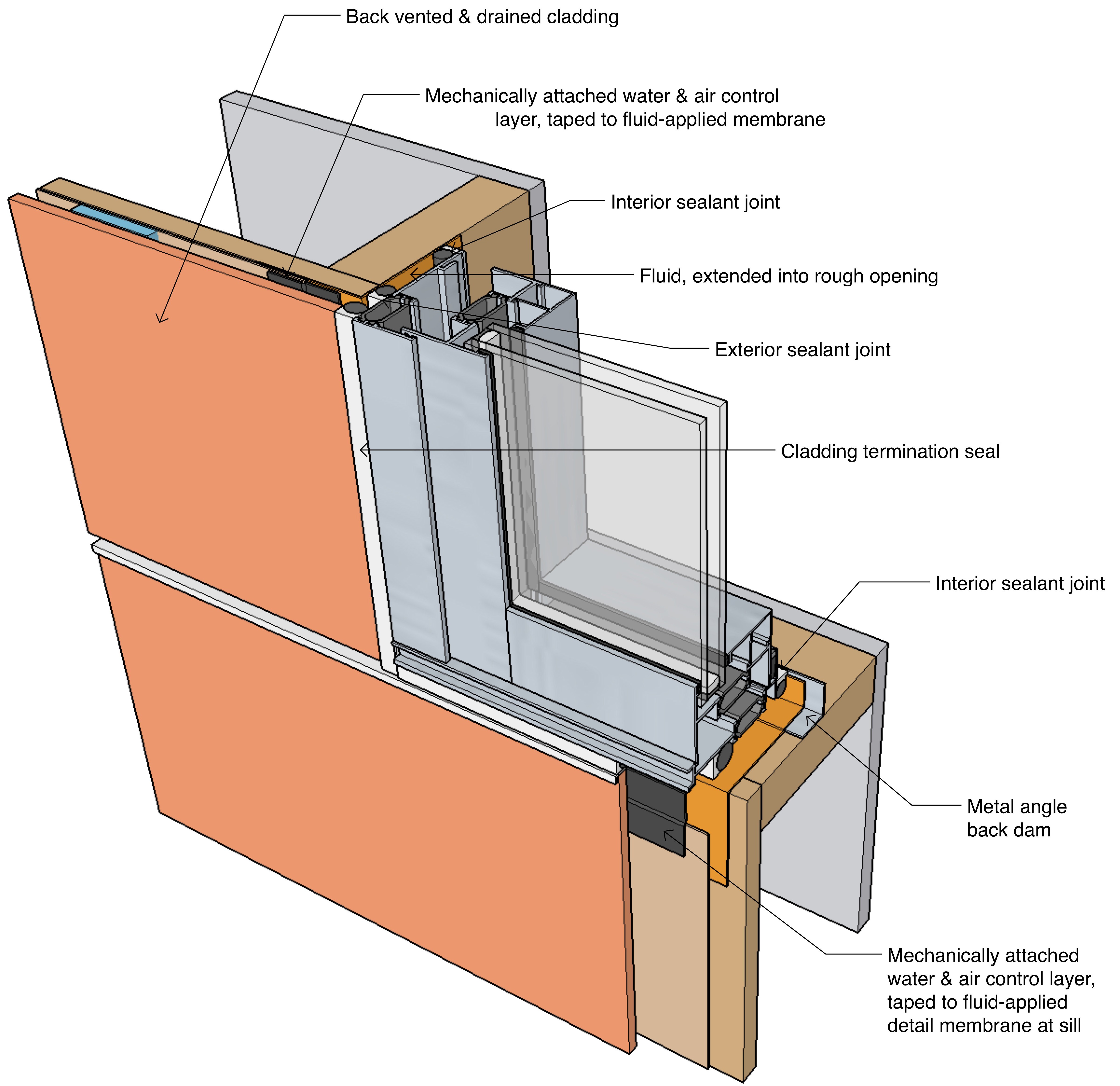
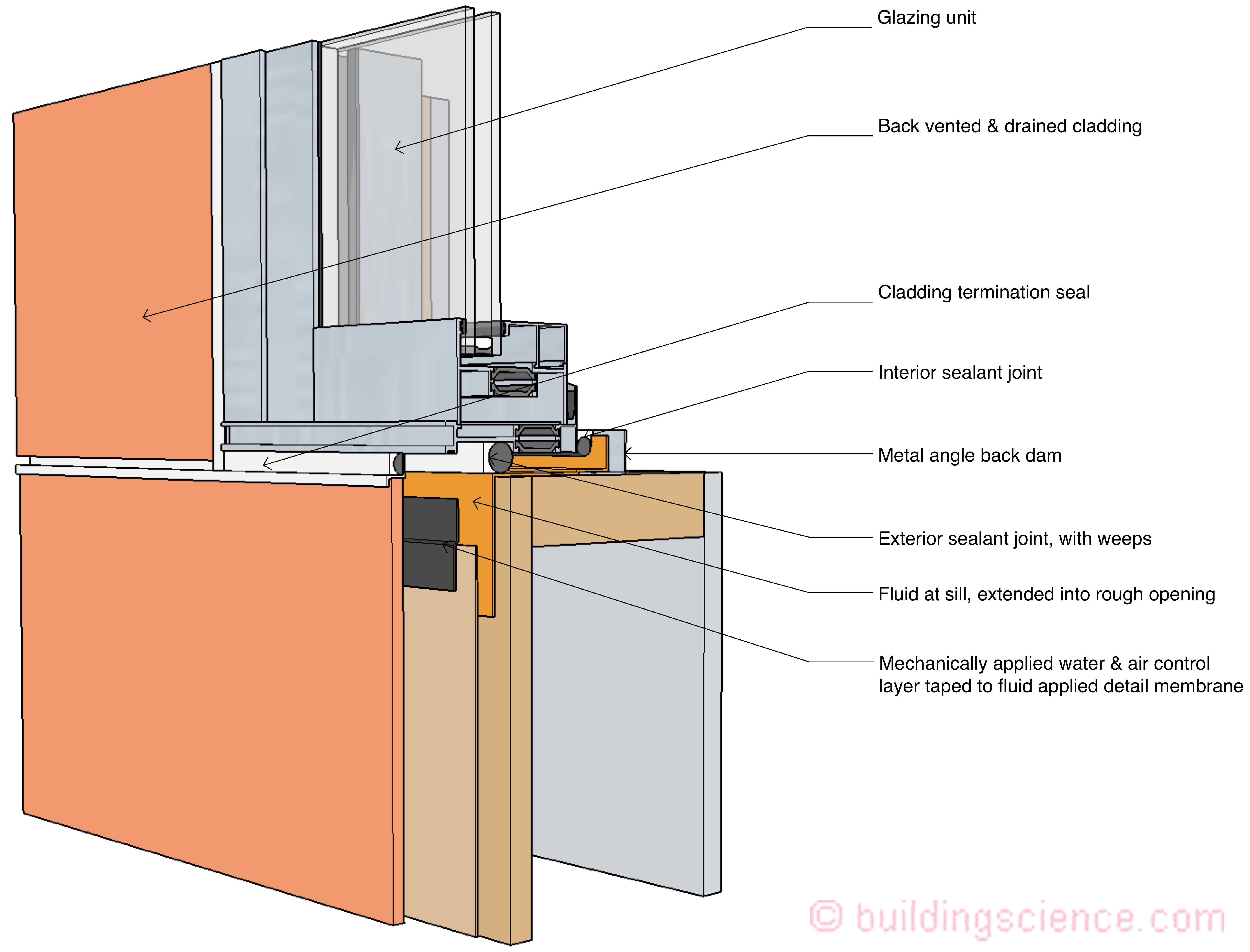
Figure 4a, 4b and 4c: Mechanically-Attached Water and Air Control Layer Coupled with a Fluid-Applied Flashing- Note the fluid seal over the head flashing. The fluid seal could also be replaced with a membrane flashing tape. Also note that the mechanically-attached water and air control layer extends over the top of head flashing and seal. This mechanically-attached water and air control layer should not be sealed at its bottom edge at the head of the window to allow incidental water that penetrates the mechanically attached water and air control layer to drain out at the head. Finally, note the “shingling” of the “taped” mechanically-attached water and air control layer at the sill.
OK, on to self-adhered membrane rough opening flashing linings…aka “flashing tapes” coupled with a mechanically-attached water and air control layer (Figure 5a, Figure 5b and Figure 5c). This is probably the most “conventional” of the approaches. Flashing tapes have been around a long time and have had excellent performance…in “simple openings”. They are very “skill sensitive” and not everyone is good at the “origami” necessary at “punched openings” where the windows are “innies” on “terraced” sill framing…. In complex punched opening geometries fluid-applied flashings rule. In simple openings flashing tapes are still the “go to” approach…for good reasons…hard to argue with excellent historic performance. In this sequence note that the self-adhered membrane flashing tape at the window head extends into the opening and that the head flashing is installed over this membrane strip. This reduces air leakage at the head as the mechanically-attached water and air control layer is not sealed at the head.
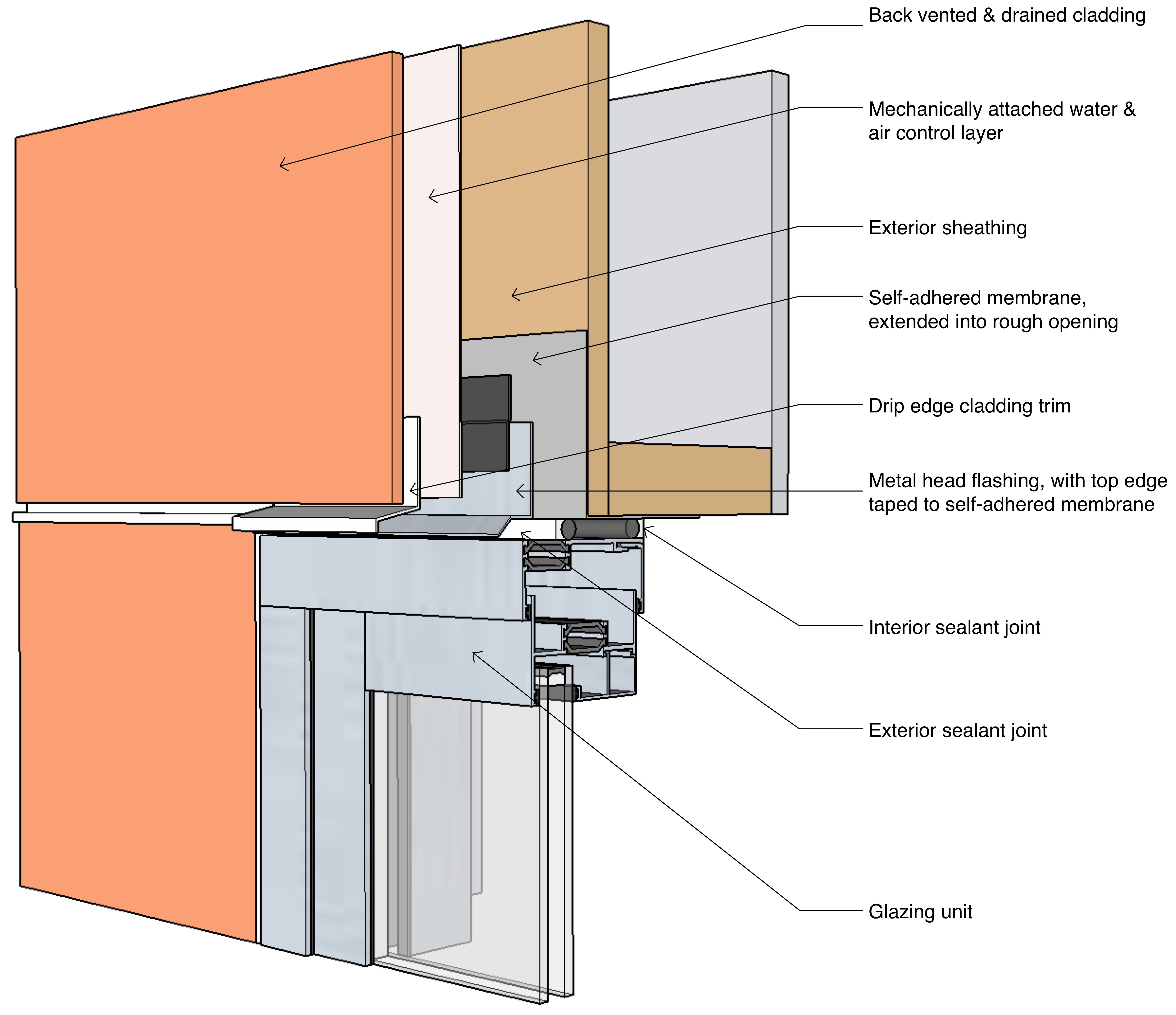
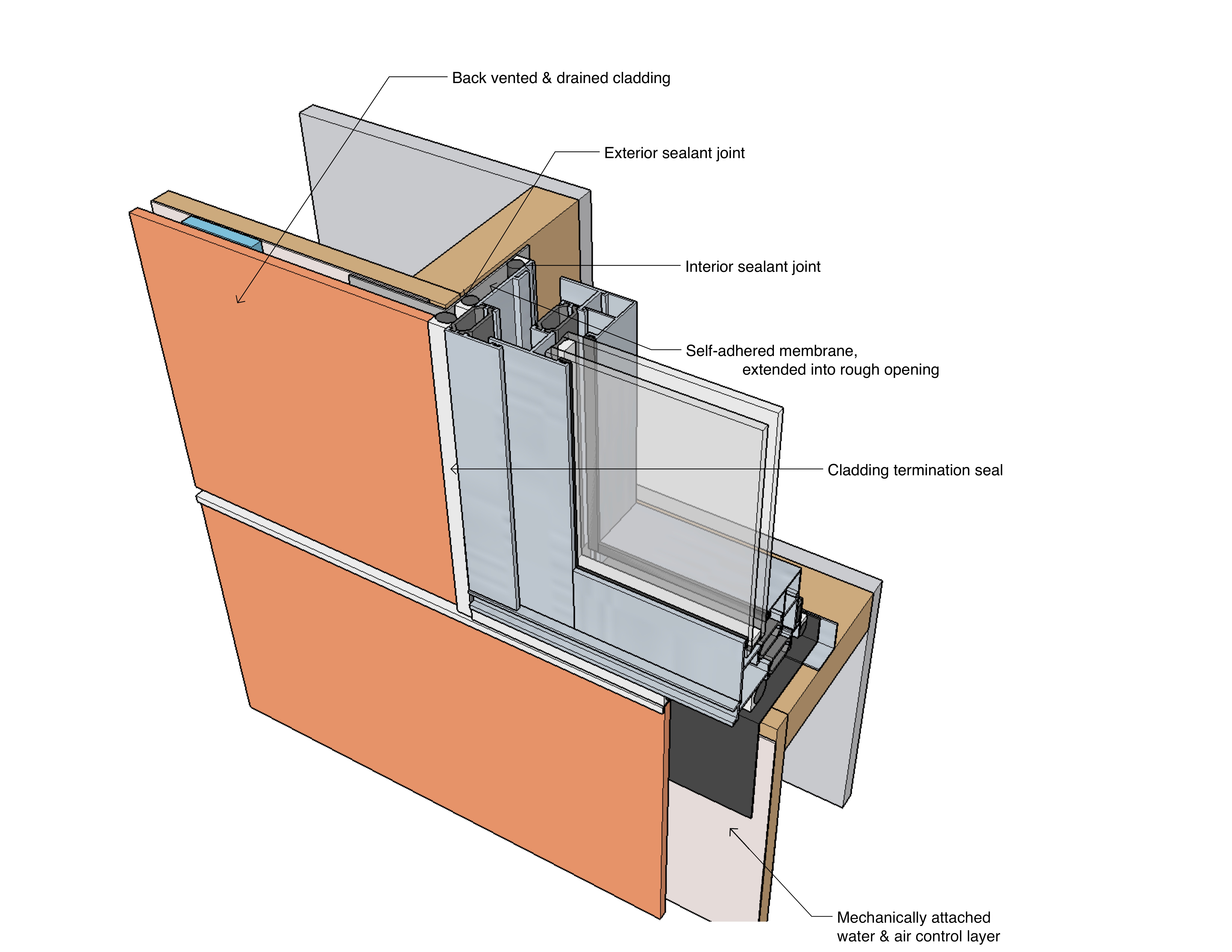
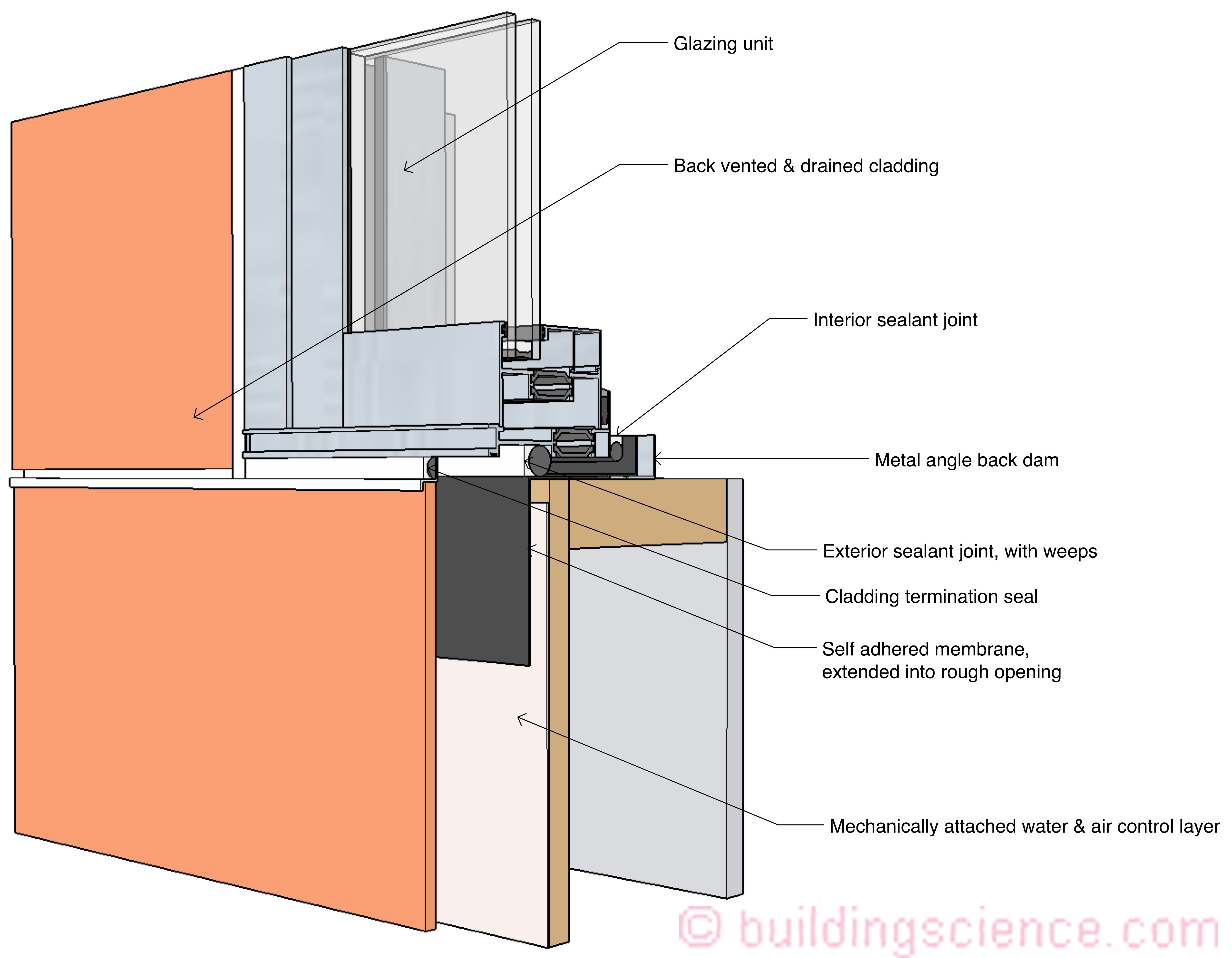
Figure 5a, 5b and 5c: Self-Adhered Membrane Rough Opening Flashing Lining Coupled with Mechanically-Attached Water and Air Control Layer- In this sequence note that the self-adhered membrane flashing tape at the window head extends into the opening and that the head flashing is installed over this membrane strip. This reduces air leakage at the head as the mechanically-attached water and air control layer is not sealed at the head.
Finally, we are on to continuous insulation with both “innie” and “outie” windows. The “innie” windows are the easy ones (Figure 6a, Figure 6b and Figure 6c). All that we have going here is taking the exact same approach in Figure 4a, 4b and 4c (a mechanically-attached water and air control layer coupled with a fluid-applied flashing extending into the “rough opening”) and adding continuous insulation. The key take away’s are the “cladding trim” closure at the perimeter of the window opening and a “strong recommendation” to use a “bumpy” or “textured” mechanically-attached water and air control layer be used in order to create a “gap” between the continuous insulation and the sheathing to allow for “hygric redistribution”…The rationale for this was covered way back when (“Mind The Gap, Eh”, ASHRAE Journal, January 2010). Note that this “gap” is not necessary with mineral wool or stone wool continuous insulation due to its high vapor permeance.
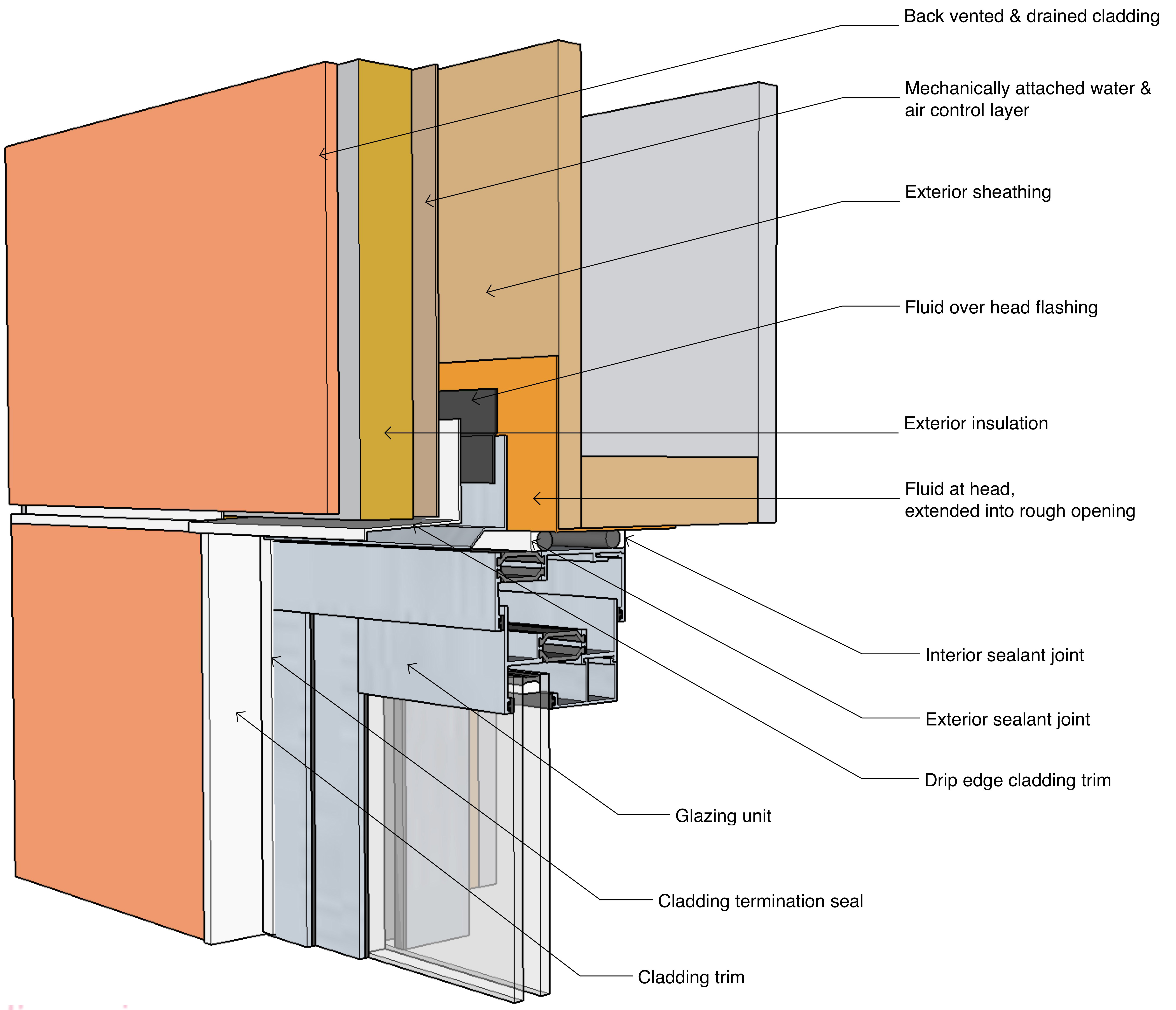
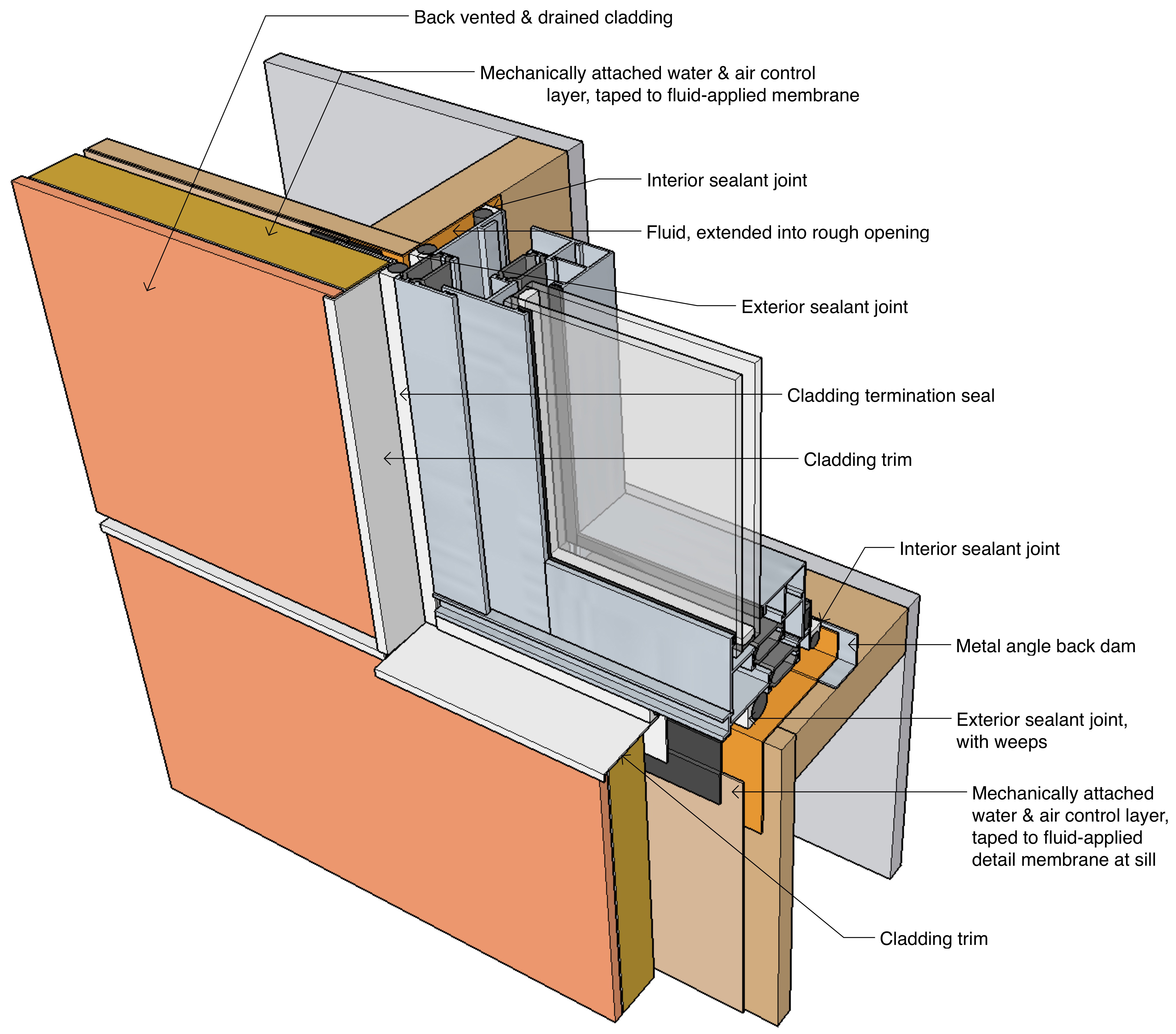
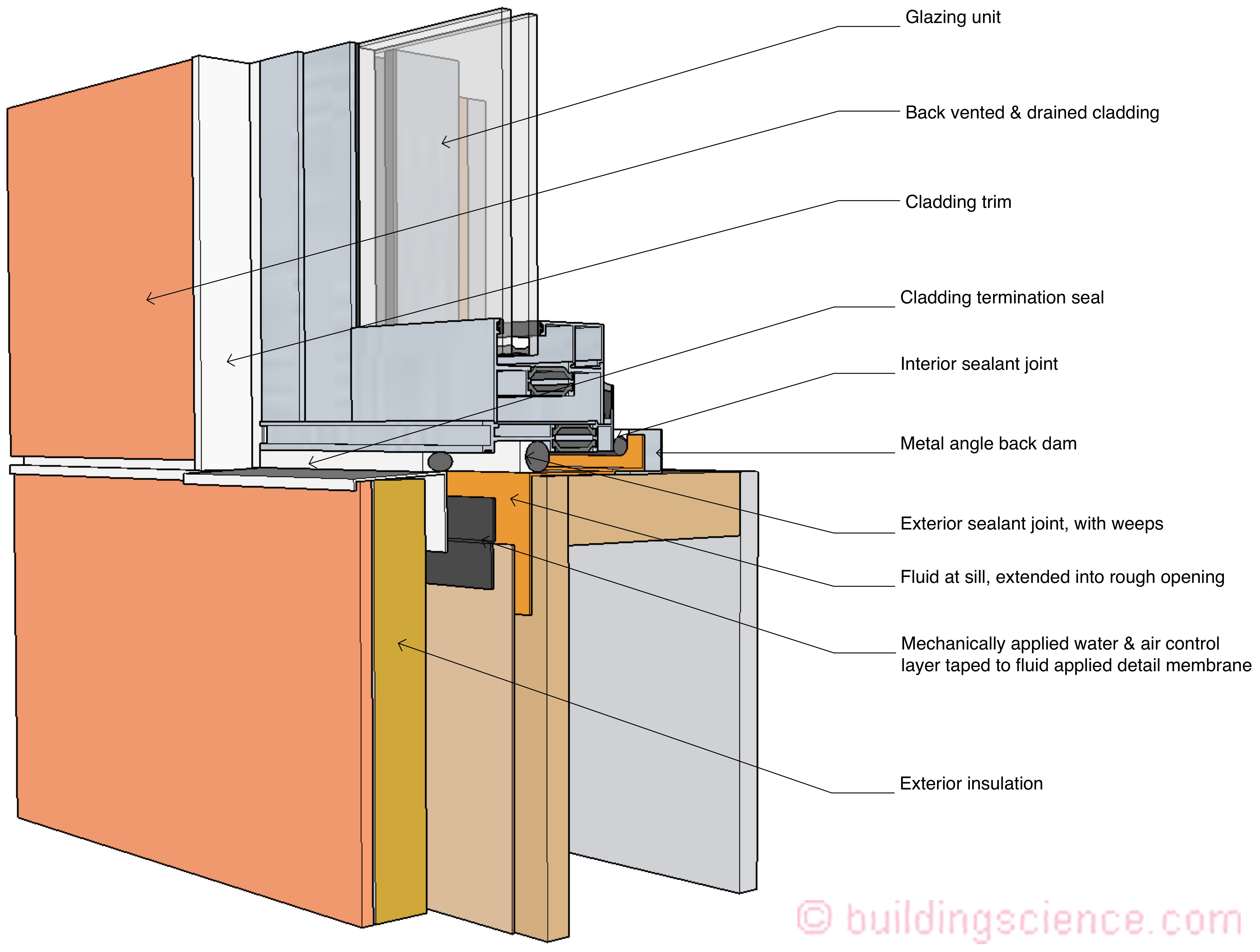
Figure 6a, 6b and 6c: Continuous Insulation with “Innie” Windows – This is the exact same approach as in Figure 4a, 4b and 4c (a mechanically-attached water and air control layer coupled with a fluid-applied flashing extending into the “rough opening”) but with adding continuous insulation. The key take away’s are the “cladding trim” closure at the perimeter of the window opening and a “strong recommendation” to use a “bumpy” or “textured” mechanically-attached water and air control layer be used in order to create a “gap” between the continuous insulation and the sheathing to allow for “hygric redistribution.”
Last, we come to continuous insulation with “outie” windows. With windows located “outboard” and flush with the cladding system lining the rough opening with plywood becomes necessary for both structural and water management and air management reasons (Figure 7a, Figure 7b and Figure 7c). The plywood lining extends outward to line up flush with the exterior surface of the continuous insulation. The only approach that seems to work is to coat/seal the plywood lining with a fluid-applied flashing system extending into the opening and outward to the face of the exterior sheathing. In this sequence of details a fluid-applied water and air control layer is installed over the exterior sheathing. Note the use of “cap nails” to create a “gap” similar to the gap recommended in Figure 6a, Figure 6b and Figure 6c. If a “bumpy” or “textured” mechanically-attached water and air control layer is used then the cap nails become unnecessary.
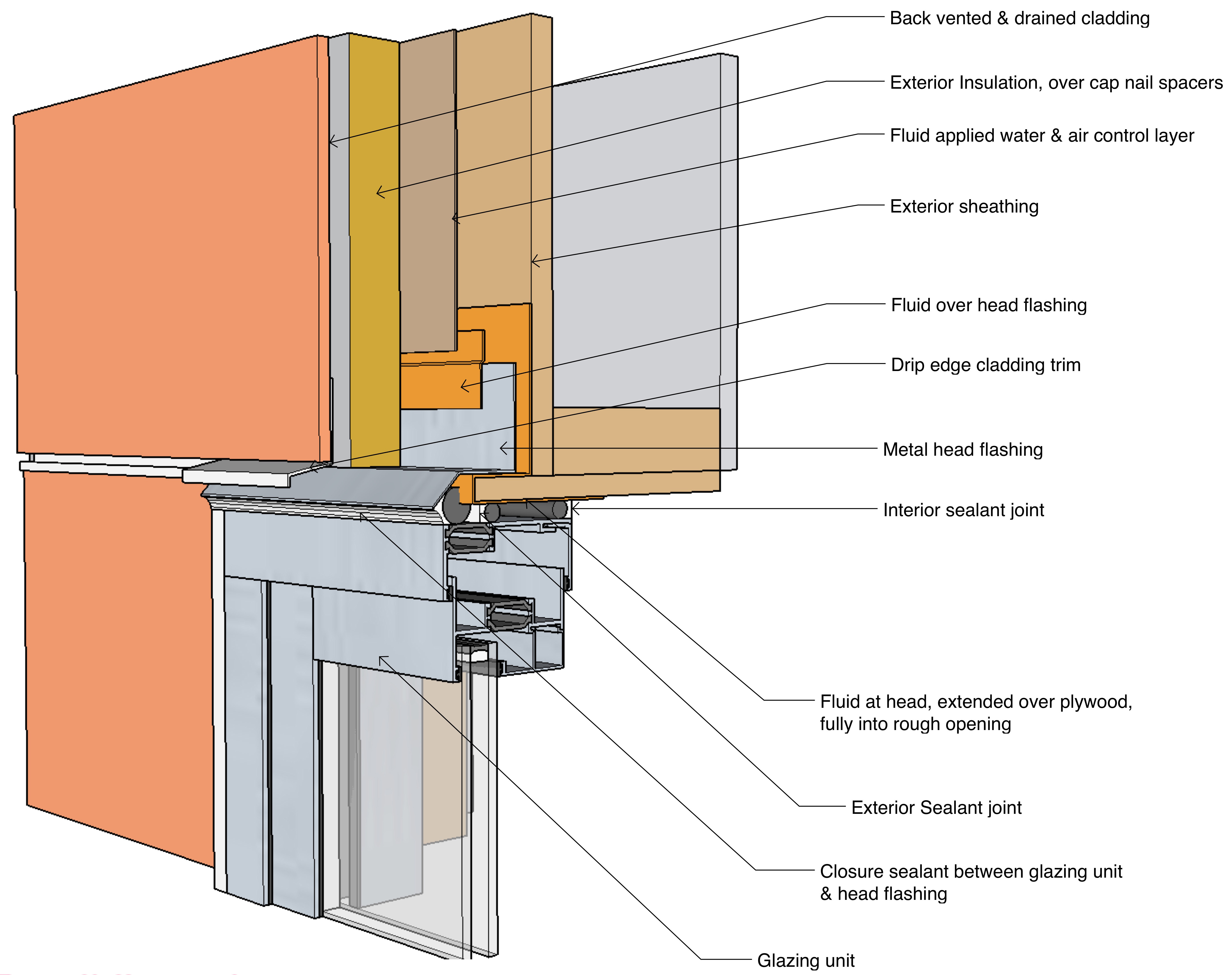
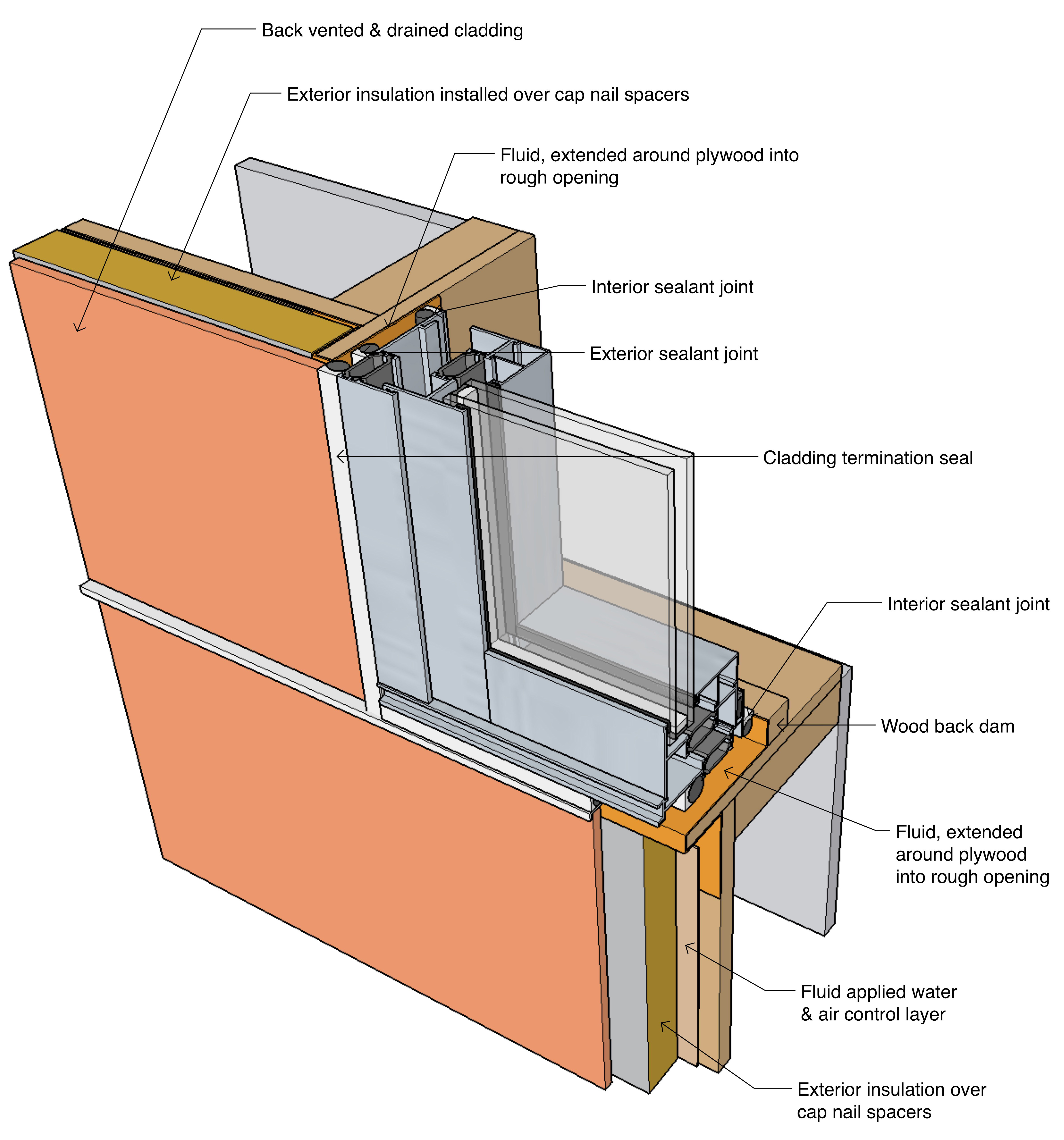
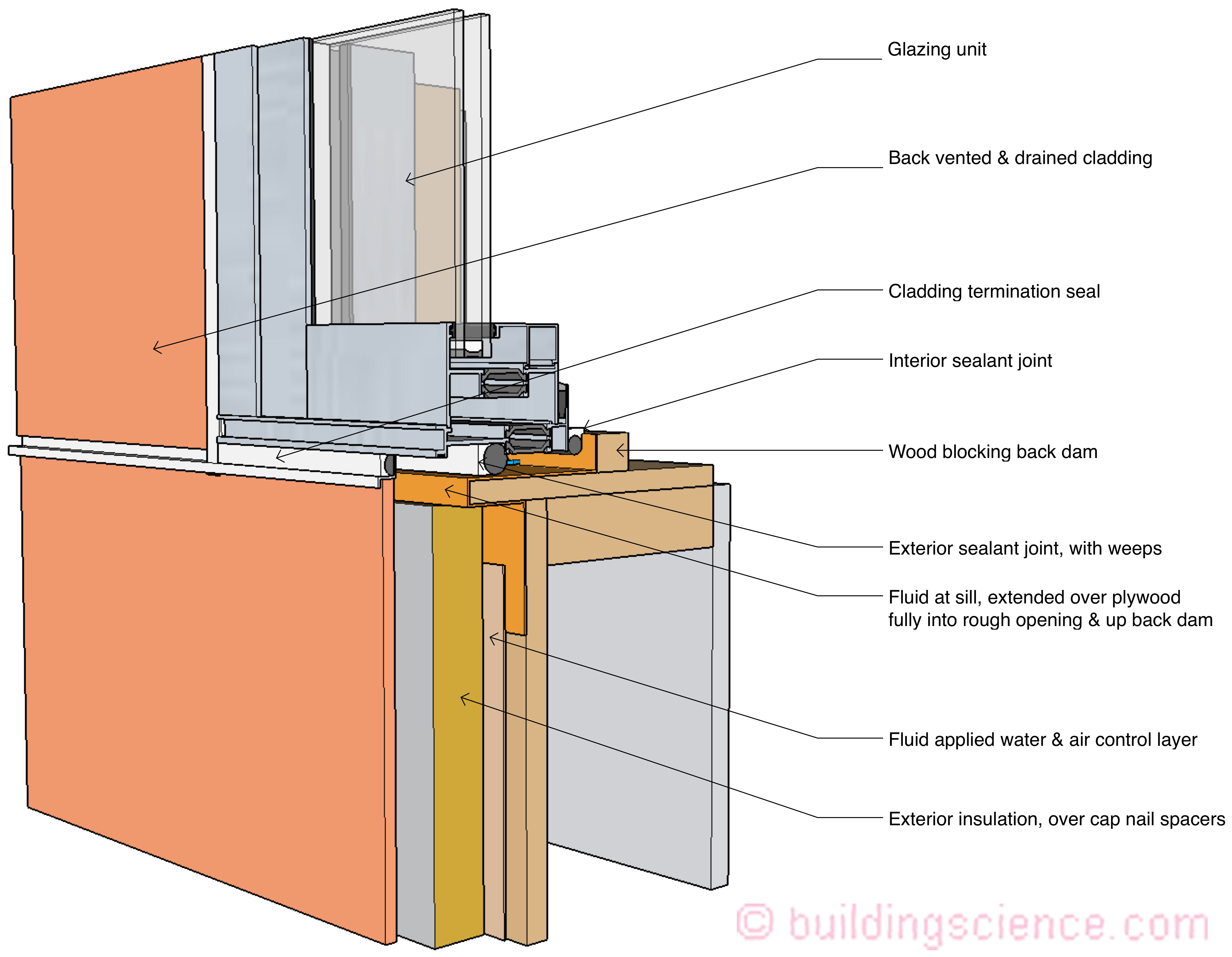
Figure 7a, 7b and 7c: Continuous Insulation with “Outie” Windows– With windows located “outboard” and flush with the cladding system lining the rough opening with plywood becomes necessary for both structural and water management and air management reasons. The plywood lining extends outward to line up flush with the exterior surface of the continuous insulation. It is necessary to coat/seal the plywood lining with a fluid-applied flashing system extending into the opening and outward to the face of the exterior sheathing. In this sequence of details a fluid-applied water and air control layer is installed over the exterior sheathing. Note the use of “cap nails” to create a “gap” similar to the gap recommended in Figure 6a, Figure 6b and Figure 6c. If a “bumpy” or “textured” mechanically-attached water and air control layer is used then the cap nails become unnecessary.
Whew! I think we are done with this “punched opening” stuff and unflanged windows….I will leave the unflanged doors to another time…probably tie them in with “store front” systems and “curtain wall” connections to “real” walls….
Footnotes:
[1]Note that the United States is back in the manufacturing game again…and I would argue never left…
[2]“a hole or a notch from a perforating operation…” from the Merriam-Webster Dictionary
[3]When my dad first came across the big pond he couldn’t get a job as an engineer even though he was one…he started out as a farm laborer near London, Ontario and then became a “tool and die” maker in Toronto. He loved that job. I grew up with a machine shop in the garage. We had a huge “punch press.” Mom finally had enough with the machine oil everywhere…I think it was the smell that got to her…and made dad get a job at de Havilland Aircraft as an engineer. I am a second-generation engineer…and immigrant…somehow it seems important to point that out…
[4]What we really have going on is three sealant joints. Two that are a big deal and one that is aesthetic. When the contractor “buys” the contract documents the contractor is buying three sealant joints. Let me repeat…there are three sealant joints…