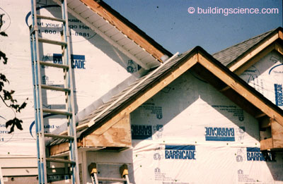
One of the dirty little secrets that never gets talked about is that water leaks through building papers, building wraps and housewraps and runs down between them and the sheathings that they cover. The water enters through nail holes and staple holes and sometimes just through the field of the material if you have a poor product.1 The good news is that the nail holes and staple holes don’t leak too much and we know how to handle the incidental leakage.
In the field of the wall we don’t care if things get a little wet as long as they can dry. We promote drying to the outside by leaving an air gap between the cladding and the building wrap or house wrap or water resistive barrier (wrb) or whatever we are calling this “thingy” this month. I like to call it the water control layer. Whatever. Anyway, the gap does not have to be very large – ¼-inch to 3/8-inch works just fine. This gap also controls hydrostatic pressure.2
At penetrations such as windows and doors (Figure 1) we have learned to “scrape the water off the sheathing at the tops of the windows by taping the top flange of the window directly to the sheathing under the building wrap (Figure 2). This is a big deal. If we didn’t do this the water running behind the building wrap would wet the top of the window opening interior finish and folks would see it. We don’t care if this water leaks through a joint in the sheathing in the field of the wall because the wet spot isn’t seen by anyone. And if the wall is designed to dry either to the interior or exterior or both it does not matter anyway.3 Recall, that this amount of water is small.
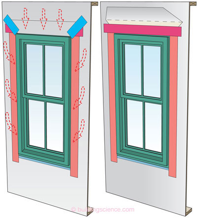
Figure 1: Water Entry at Window Opening (left) – It is important to address water running behind building wraps and housewraps at window heads and the sides of window openings.
Figure 2: Control of Water at Window Head (right) – The top window flange is taped directly to the sheathing with “flashing tape”. Note how the building wrap or housewrap is cut and folded upwards to expose the sheathing so that the “flashing tape” can be installed. Once the tape is installed, the flap is folded back down. This works exceptionally well.
At the sides of windows we use a “bedding joint”. I love this term. A heavy bead of sealant is installed behind the flange of a window and it acts like a “gasket” smushing the building wrap against the sheathing limiting the water that can run sideways into the opening (Figure 3).
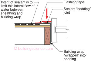
Figure 3: Control of Water at Window Jamb - A heavy bead of sealant is installed behind the flange of a window and it acts like a “gasket” smushing the building wrap against the sheathing limiting the water that can run sideways into the opening. The “red arrow” shows the “smush” direction created by screwing the window flange into the sheathing and frame opening.
And all of this works. And it works well. Building wraps and housewraps have a long history of successful performance. But understand that in order for them to work they rely on tapes and sealants - and by the way they leak… but not enough to get your knickers in a knot. All in all they provide a very robust system that is hard to beat cost wise and performance wise. Having said that there are limitations to the technology. The systems are not good for high rises because of wind loading. The wraps flutter and tear and can’t take the wind load. And with complex geometries at “punched openings” trades need to learn “origami” to wrap openings. However, wherever there are limitations there are opportunities. More on this later.
So what is wrong with just relying on a “gravity lap” (aka – layering things shingle fashion)? Gravity works, it is reliable, never needs maintenance and the politicians haven’t figured out how to tax it….yet. Well, without some kind of sealant at vertical joints at “punched openings” gravity laps alone just do not work. Check out what we have to do at a window opening to try to make the gravity lap work (Photograph 1 and Photograph 2). How wide do you have to make the vertical flashing at the jambs (“sides”) to handle the flow where the building paper butts up to the window frame? This has never worked where it rains. So it is used where it doesn’t rain - like Las Vegas and Phoenix. With the advent of building wraps and housewraps that can be taped these issues disappeared. It got even better when flashing systems became formable and flexible (Photograph 3). And better still when liquid applied systems were developed (Photograph 4).
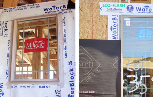
Photograph 1: Gravity Lap Part I (above left) – The flashing strips are layered shingle fashion. Horizontal bottom sill first. Vertical side jambs next. Horizontal head flashing last. Note the sealant used to provide water control layer continuity between the window unit and the flashing strips.
Photograph 2: Gravity Lap Part II (above right) – The rolls of building paper are installed horizontally shingle fashion. The vertical edge of the building paper is sealed to the edge of the window unit with more sealant. Any water that enters at that joint is expected to be controlled by running down the vertical “side flashing” or jamb flashing and out at the bottom. The width of the jamb flashing is problematic. That is why the flashing tape and housewrap detail at the window jamb flange shown in Figure 2 (and in Sidebar I) is such an improvement.

Photograph 3: Formable Flashing (above left) – Life got better when flashing systems became formable and flexible. This photo dates back a decade to when I got my first sample of flexible flashing to play with in my back yard. I thought it was the greatest invention since the transistor. Ok, so I am exaggerating - but only a little. Look at how beautifully a seamless under window flashing system is created.
Photograph 4: No Origami Here (above right) – Today’s liquid applied systems easily handle complex geometries seamlessly.
In commercial and institutional buildings we have come to rely on fully adhered membranes and liquid applied membranes (Photograph 5 and Photograph 6). By adhering directly to the sheathing the wind load issues become moot. And with no gap between the water control layer and sheathing we don’t have to worry about water that enters through fasteners wandering around between the two layers. But we had to learn a great deal about how to get the membranes to “stick”. We found we had to “prime” concrete and masonry block surfaces to get things to stick. And when we had “reverse laps” we had figure out a way to “terminate” the lap - otherwise it would “fishmouth” and begin to peel away. In the early years it was so bad we used to call “peel and stick” membranes “stick and peels”. When these products were first introduced in commercial buildings they had horrible reputations. Now they are the gold standard. But it took almost 20 years and major advances in adhesive technology.

Photograph 5: Fully Adhered Membrane (above left) - In commercial and institutional buildings fully adhered membranes are the “gold standard”. But it took 20 years. These are now true “peel and stick” systems when primers are used.
Photograph 6: Liquid Applied Membrane (above right) - Becoming common now. Note the joint treatment – a tape reinforced mastic is installed at the joints first – then over coated with a liquid applied membrane creating as seamless, jointless system.
This “terminate” the “reverse lap” thing is a big deal. There are a couple of ways we have learned to do this. In commercial buildings we often use “pressure bars” or a continuous bead of sealant to glue the top edge of the reverse lap to the underlying membrane or sheathing (Photograph 7). A pressure bar is just what it sounds like – a strip of metal with a gasket attached to it that is mechanically fastened though the layers to the structure compressing a gasket to seal the reverse lap.4 We have to thank the roofing industry for this technology. Nice job roofers.
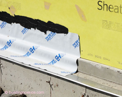
Photograph 7: Termination – This “terminate” the reverse lap thing is a big deal. A continuous bead of sealant is used to glue the top edge of the reverse lap to the underlying membrane or sheathing.
Adhesives have come a long way in my lifetime. We glue planes together, cars together, bridges together and tissues together. And we have made them resistant to heat and ultra violet light and compatible with almost anything. But with all of the advances in materials science we have still not figured out how to get things to stick to mud, dirt and frozen surfaces. Let me repeat this because as good as things are there is no way to stick stuff to muddy, dirty, cold, wet and frozen surfaces. I should repeat it again, but you folks should just stop here, re-read the pervious sentence and think about it. Re-read it again. OK, now lets move on.
Residentially we now use tapes on wood sheathings (Photograph 8) and foam sheathings (Photograph 9) to provide water management and air management. So how well do these systems actually work? Now? Real well. In the early days? Not so good. The residential tape systems had to go through the same learning curve the commercial membrane systems went through.5

Photograph 8: Wood Sheathing (above left) - Residentially we now use tapes on wood sheathings that have factory applied membranes factory bonded to them to provide water management and air management.
Photograph 9: Foam Sheathing (above right) - Foam plastic sheathing panels are taped together creating a water-resistive barrier system. These systems are now around 20 years old. This image dates back to a subdivision development in Chicago in 1995. 3M was one of the first to develop acrylic based tape system for housewraps in the 1980’s and they migrated to foam sheathings in the 1990’s.
Tapes are typically a carrier sheet, which provides strength, and the adhesive which provides the “sticky”. Carriers are often made of polyethylene or polypropylene, but can be made of aluminum foil or other materials. Flashing tape manufacturers are advancing the technology by fine tuning both the carrier films (“facers”) and adhesives.
There are two basic groups of adhesives used in tapes – butyl and acrylic. Most butyl tapes are typically called “flashing” tapes and the acrylic tapes are typically called “sheathing” tapes. The butyl tapes are “thicker” and are “gooey” on the back. The acrylic tapes are very thin. The butyl tapes handle movement better than the acrylic tapes. The acrylic tapes “stick” better – they stick unbelievably well. The acrylic tapes are often used to “terminate” the top edge of a butyl tape. This is necessary as butyl tapes can fishmouth – their top edge peels away or roll away over time - as such their top edge needs to be “terminated”. This type of fishmouthing with acrylic tapes does not occur. Although most flashing tapes are butyl, advances in acrylic technology have allowed a limited number of acrylic tapes to function as both flashing tapes and sheathing tapes.
Today’s tapes are resistant to UV and heat and rain. How do we know? We stick them outside for years and watch them and we also take apart older buildings that have used them to see how well they did (Photograph 10). Nothing beats real world exposure (Photograph 11, Photograph 12 and Photograph 13). The real world exposure testing is used to develop (“calibrate”) short term “accelerated aging tests”.6

Photograph 10: Fifteen Year Old Tape – This is my house. I took things apart at a few locations last summer to have a look at how things were working out. The tape, which is acrylic based, looks brand new and is sticking like it is brand new. The wood furring has aged, but not the tape. I am a believer. Wasn’t that was a Monkey’s hit recorded in 1966?
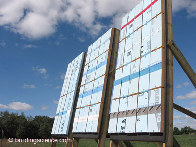
Photograph 11: Building Science Corp “Skunkworks” Exposure Facility – To test tape resistance to UV and heat and rain we stick them outside for years and watch them. The real world exposure testing is used to develop (“calibrate”) short term “accelerated aging tests.”
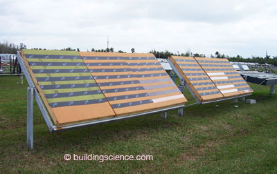
Photograph 12: Proprietary Florida Exposure Test Site - Not one of our sites. Lots of folks are testing things this way. Especially the folks who make things to sell. Nothing beats real world exposure.
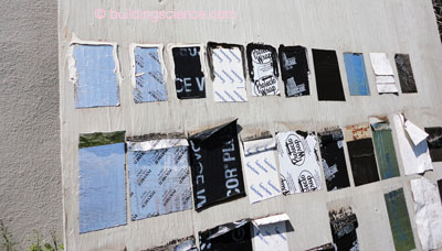
Photograph 13: Horizon Homes Test Panel - You would be surprised at the number of homebuilders who are testing the stuff they plan to use to see how it works. Our rule-of-thumb is that if it works exposed like this for 2 years you are pretty much good to go.
The term “acrylic” is deceptively simple and does not give justice to the evolution of the materials science behind it. Acrylic adhesives are based on acrylic polymer chemistry just like many high performance caulks and paints. The polymerization is “tunable” such that variables such as softness, hardness, low temperature flexibility and adhesion strength can be optimized. What all this means is that today’s acrylic tapes can handle the movement of the wood based sheathings and foam sheathings – mostly because they move in tandem with the sheathings as opposed to fighting them – coefficients of expansion are “tuned” to the substrate. The elasticity of the adhesive compensates for the movement of the substrate due to changes in temperature and moisture content.
The “flashing” tapes are typically butyl rubber based (some are acrylic based as previously mentioned). The rubbers are synthetically produced and thus like the acrylics are also “tuned” to enhance performance. They are formulated compounds that allow you to add “tackifiers” to improve adhesion.
Both acrylics and butyl tape systems have UV stabilizers to address solar exposure and antioxidants to address long term aging which can change properties over time. In a twist to typical perceptions the tape systems tend to be as - or more durable - than the building wraps and housewraps they are adhered to.
With any tape for it to function well it must be firmly pressed into place. This is particularly important with acrylic tape systems. They should be installed with a roller.
What’s next? We see it already in the commercial side. Sealants and “paintable tapes” replacing tapes entirely. Installing a sealant in the joint and then painting over or spraying over the joint sealant. Sometimes a mesh reinforcing is used, sometimes not. Sometimes just a spray applied tape. How are they working out? Ah, a little too soon to tell with some systems. I like the sealant in the joint covered with a mesh reinforcing then all of this painted over. But then again I am old school on this stuff.
Back to this termination thing. With flashing tapes we tend to terminate them two ways – with either a sheathing tape or a bead of sealant (Photograph 14 and Figure 4). A sheathing tape does not need to be terminated – it terminates itself.


Photograph 14: More Termination (above left) - With flashing tapes we tend to terminate them two ways – with either a sheathing tape or a bead of sealant. A sheathing tape does not need to be terminated – it terminates itself.
Figure 4: Termination of Flashing Tape (above right) – The “red” horizontal tape is a butyl based “flashing tape” that is “terminated” by a “green” acrylic based “sheathing tape.”
At the end of the day taped sheathings work as well as building wraps and housewraps and vice versa. But there are limitations to both. With building wraps and housewraps the biggest single problem is making sure gravity laps are actually used. Amazing as it seems reverse lapping is still the most common residential construction defect I see (Photograph 15). Despite all the education and training in the world it still happens…go figure.
Photograph 15: Reverse Lap - With building wraps and housewraps the biggest single problem is making sure gravity laps are actually used. Look at the step flashing in this photograph. It should be “tucked under” the housewrap. Amazing as it seems reverse lapping is still the most common residential construction defect I see. Despite all the education and training in the world it still happens…go figure. In a delicious bit of irony, this type of defect is often fixed after the fact by a strip of flashing tape sealing the step flashing to the housewrap. The flashing tape is then “terminated” with a strip of sheathing tape at its top edge.
With tapes the biggest single problem is folks thinking they can stick them to muddy, dirty, cold, wet and frozen surfaces. You would think this is obvious. Again, amazing as it seems, folks keep trying to do it.
Check out Side Bar I and Side Bar II to see how to do it “right” with two of the more common “proven” approaches using either a housewrap or insulating sheathing as the water control layer.
The moral of this story is that when done well, there are a number of approaches that can work – but none of them work if put together wrong or put together dirty. With all these approaches the technology is not the problem, people are. Seesh. So folks, don’t do stupid things and it will all be ok.
Sidebar I: Installing Windows in Housewrap Openings
A) Install beveled wood siding in frame wall opening at sill to create slope; (B) “I” cut in housewrap; (C) Fold housewrap in at jambs and sill; housewrap at head temporarily folded up; (D) Install formable flashing at sill; (E) Install sealant bead at head and jambs; install window plumb, level and square; (F) Install flashing tape at jambs; (G) Install flashing tape at head; (H) Fold housewrap down at head; tape in place with sheathing tape; (I) Interior view prior to window installation; (J) Interior view after window installation; (K) Air seal window around entire perimeter on interior with sealant and sealant backer rod
Sidebar II: Installing Windows in Insulating Sheathing Openings
(A) Insulating sheathing installed over frame wall; (B) Install beveled wood siding in frame wall opening at sill to create slope; (C) Install formable flashing at sill; (D) Install window plumb, level and square; (E) Install flashing tape at jambs; (F) Install flashing tape at head; (G) Install sheathing tape over flashing tape at head to terminate flashing tape; (H) Interior view prior to window installation; (I) Interior view after window installation; (I) Air seal window around entire perimeter on interior with sealant and sealant backer rod
Footnotes:
We looked at some of the material properties of these products in “BSI-066: Leaks & Holes." What is bemusing to me is that of all of the myriad of material tests done to qualify these products such as resistance to hydrostatic head the entire point is missed in that the weak spot is the nail hole. If the tests made sense you would test the materials with nail holes and staple holes – a true system test.
We looked at this in “BSI-057: Hockey Pucks & Hydrostatic Pressure.”
People seem to live in this fantasy world where they believe that walls don’t leak. Almost all of them do. But it doesn’t matter if they dry before any damage occurs. This balance between wetting and drying is a big deal and it is getting more complicated every day as we reduce energy flows across assemblies thereby reducing drying potentials. Having said that, we still have a lot of capacity and robustness left in most assemblies if we don’t do stupid things like install vinyl wall coverings and plastic vapor barriers in climates that don’t need them or assemblies that don’t need them.
A pressure bar and a gasket? Wow. Why is something so “serious” needed in a commercial building? Well, when you are up 20 floors the “loads” are an order of magnitude greater than when you are up 2 floors. And with commercial buildings the hygric buffering is significantly lower. “Hygric buffering”? Nice new popular phrase that means storage and redistribution. I can store a great deal of incidental water in wood framing and wood sheathing – I can’t store squat in a steel stud or gypsum sheathing. A tiny leak in a high rise made out of glass and steel and gypsum that “sees” big “loads” is a much bigger issue than a tiny leak in a low rise made out of wood and wood products.
And the same learning curve the residential and commercial housewrap and building wrap folks went through. How easy folks forget the problems with UV exposure and surfactants and blow off and incompatibility with sealants. Today’s systems are awesome, but 20 years ago they mostly sucked. Heck, even as recently as 10 years ago wood sugars, tannins and other surfactants drove folks crazy.
I am old school. It is hard to beat taking a building apart after 15 or 20 years and having a peak. We have been doing this stuff for around 20 years and that is why I am now comfortable with the technology. The two decades of experience “tunes” the accelerated aging stuff and system evaluation stuff to the point where I now believe it. See the testing protocols and evaluation protocols in the References section of this column.
References
AC 71 – ICC-ES Acceptance Criteria for Foam Plastic Sheathing Panels Used as Water-Resistive Barriers
AC 212 – ICC-ES Acceptance Criteria for Water-Resistive Coatings Used as Water-Resistive Barriers Over Exterior Sheathing
AC 310 – ICC-ES Acceptance Criteria for Water-Resistive Membranes Factory-Bonded to Wood-Based Structural Sheathing, Used as Water-Resistive Barriers
Grin, A. and J. Lstiburek; Guidance on Taped Insulating Sheathing Drainage Planes: Final Report, December 2012

