This article is the fourth in a series on various building diagnostic tools and techniques to sleuth out problems in buildings.
Introduction
Back again, with more tools of the trade and techniques that I use for forensic examinations and diagnostics of problem buildings (see How to Look at a House like a Building Scientist (Part 1:Air), How to Look at a House like a Building Scientist (Part 2: Heat), and How to Look at a House like a Building Scientist (Part 3: Temperature, Humidity, and HVAC Systems) for more). The rough breakdown that I’m using for these columns is the topics of air, heat, and moisture: this time, we’re looking at water and moisture.
Water, Buildings, and the Importance of Deflection
Water and moisture problems are the most common cause of building durability issues or damage to buildings. Within the category of moisture, the most damaging is liquid water, typically in the form of precipitation (rain) or groundwater. Second is air leakage, and the associated air-transported moisture—such as condensation inside walls and roofs. A distant third is moisture vapor problems—such as wetted reservoir cladding issues such as brick with solar-driven moisture. https://www.greenbuildingadvisor.com/article/when-sunshine-drives-moisture-into-walls
But getting back to rain control in buildings, we often refer to the three “D”s of rain control:
-
Deflection: trying to keep the water off the building’s skin to begin with, before it can get in further and cause damage
-
Drainage, storage, or exclusion: the mechanism depends on the assembly type:
-
Drainage: modern drained walls (e.g., housewrap and siding, brick veneers, rainscreen assemblies, etc.) expect water to get past the exterior of the wall, where it is then handled by a water control layer or drainage plane. Water can then drain out of the assembly via a system of hidden waterproof materials (e.g., housewrap) and flashings.
-
Storage: ‘mass masonry’ walls (solid multi-wythe brick walls, stucco on CMU) have no separate drainage layer. They absorb rainwater that hits them, safely store the water, and then later dry during more favorable conditions.
-
Exclusion: ‘perfect barrier’ assemblies (glass curtain walls, insulated metal panels, single-ply membrane roofs) rely on a ‘perfect’ watertight layer on the exterior side of the assembly. If water gets past this layer, leakage results.
-
-
Drying: once water gets into the assembly, can it escape via drying or evaporation?
If you want to do a deep dive into this material, please check out John Straube’s Building Science Digest on the topic. BSD-013: Rain Control in Buildings
There is often a lack of emphasis on deflection, or keeping the rainwater off the building to begin with. Examples of deflection are shown in Figure 1: overhangs keep water off the walls, drip edges and flashings shed water from walls (reducing runoff damage), and detailing or landscaping reduce splashback damage at grade.
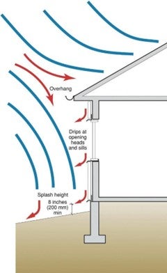
Figure 1: Rain deflection concepts in a residential wall
These are all details that have been historically incorporated into construction, but are unfortunately sometimes omitted for aesthetic reasons. Think of those modern house designs with zero overhangs. I have gotten pushback from architects who didn’t want a line of flashing interrupting their perfect flat planes. Sure, we can omit them, but you’ll end up with drool marks, water stains, and deteriorated cladding… but hey, that damage occurs after the architecture magazine photo shoot, so that’s acceptable, right?
Water Deflection in Practice
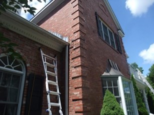
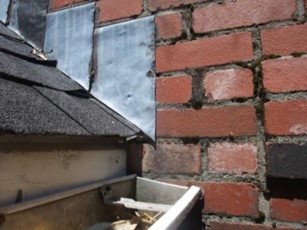
An example of a water deflection problem is a kickout flashing. Figure 2 shows a case where a downward-sloping roof terminates in the middle of a wall. Looking closer (Figure 3), you can see moss growing on the brick mortar joints—not a good sign for water issues.
|
Figure 2: Roof-to-wall interface at brick building |
Figure 3: Moss growing on brick mortar joints |
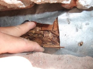
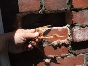
We opened up a brick, slit the housewrap (Figure 4), and the OSB sheathing showed signs of distress from long-term moisture exposure—you could pull strands off the surface by hand (Figure 5). The housewrap itself wasn’t leaking—it was just more water than this assembly could take without degradation.
|
Figure 4: OSB behind housewrap |
Figure 5: OSB strands hand-removable |
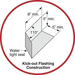
The answer, of course, is that this geometry requires a kickout flashing (Figure 6), to deflect the concentrated roof runoff away from the vulnerable wall surface. Figure 7 shows some of the critical dimensions for fabricating a sheet metal kickout flashing, or you can buy commercially made kickout flashings. https://www.dryflekt.com/
|
Figure 6: Kickout flashing in stucco building |
Figure 7: Kickout flashing critical dimensions |
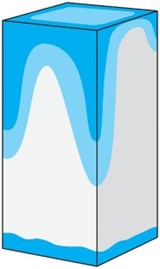
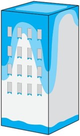
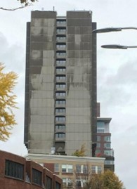
The patterns that wind-driven rain makes when hitting buildings—especially tall buildings—is pretty distinctive; my boss Joe refers to this as, “Where the building touches the ground and touches the sky.” The worst water deposition occurs at the top edges of the building and the corners (Figure 8), due to the way that wind moves the rain around these buildings. Also, water is concentrated at grade, due to splashback and/or ground water issues.
Windows add further risks: glass does not absorb water, so the majority of the wind-driven rain is shed off the window surface onto the wall below, especially at the corners (Figure 9). These stains are commonly referred to as “mustaching.” This means that window sill details are critical to deflect water concentrations off of building surfaces.
If you walk around town at the start of a rainstorm, you can see these exact patterns forming on buildings that show wetting, such as concrete surfaces (Figure 10) or by looking at window runoff with an infrared camera. How to Look at a House like a Building Scientist (Part 2: Heat)
|
Figure 8: Water deposition patterns: roof & grade conditions |
Figure 9: Water deposition patterns: adding window runoff |
Figure 10: Water deposition patterns on tall buildings |
Window Sills and Drip Edges
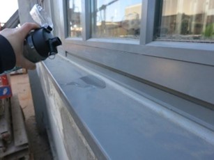
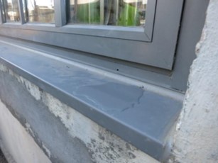
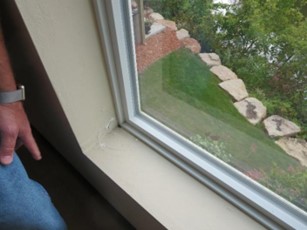
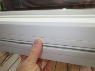
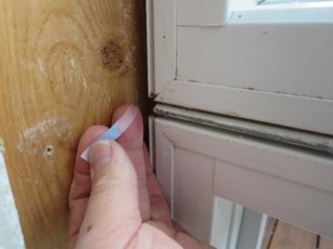
Given how important window drip edges are, it is worth testing them during construction—if you can catch them in time. All it takes is a water bottle, and you can demonstrate whether they’re sloped the wrong way, directing water towards the building (Figure 11 and Figure 12), or sloped correctly, shedding water off the surface (Figure 13 and Figure 14).
|
Figure 11: Water testing a sill with minimal slope |
Figure 12: Water testing a sill with minimal slope |
|
Figure 13: Water testing a sill with acceptable slope |
Figure 14: Water testing a sill with acceptable slope |
You can do the same type of testing on flashings: is that through-wall flashing or window head flashing getting water out of your wall, or is it a water injection system/funnel?
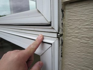
Also, this type of basic testing demonstrates the effectiveness of window drip edges. If the drip edge is pushed tight to the wall below (Figure 15), water’s surface tension will “wrap” it around the edge, and it will all end up on the wall below, instead of being ‘dripped’ away (Figure 16).
|
Figure 15: Sill drip edge pushed against wall |
Figure 16: Window runoff spills onto wall below |
The basic guidance for drip edge geometry is shown in Figure 17: a minimum projection of ½ inch beyond the wall below is required. And more projection is better—for instance, Jonathan Smegal at RDH found that a 1-¾ inch projection works better than a ¾ inch projection. https://www.protradecraft.com/when-drip-edge-becomes-double-agent. He also demonstrated that “pointing” the drip edge outward (rather than straight down) improves water shedding, as does greater “sharpness” of the edge (non-hemmed vs. hemmed sheet metal).
|
|
|
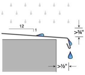
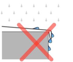
Figure 17: Sill drip edges must project a minimum of ½ inch from wall below for effective water shedding
Moisture Meters
I have two go-to moisture meters that I keep in my investigation kit.
One is a Delmhorst BD-10 “pin-based” moisture meter (Figure 18); it has two pins or probes that you stab into the wood, and it takes an electrical resistance measurement to determine moisture content. It’s typically used for wood products, but it can also be used for gypsum board.
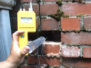
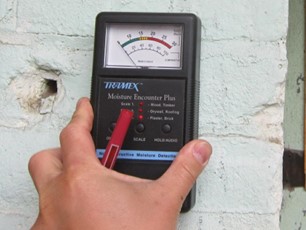
The other is a Tramex Moisture Encounter meter (Figure 19); is it a “capacitance-based meter.” It has two rubber pads placed in contact with the substrate, and the electrical response indicates the moisture content of the surface. It is used for wood, drywall, and masonry materials (plaster, brick); other versions are made specifically for concrete surface measurements. Wood MCs are measured on a 0-30% scale, and non-wood materials on a 0 to 100 relative scale. This meter also has the advantage of not leaving pinholes, if you’re working on a finished surface.
|
Figure 18: Delmhorst meter with extension probe |
Figure 19: Tramex Moisture Encounter meter |
Wood moisture contents (MCs) are reported as a “percentage by weight.” For context, some general guidelines are:
-
Below 20% MC: safe conditions, no risks of mold growth
-
25-30% MC: mold growth range, but often seasonally survivable without damage, based on BSC’s long-term monitoring projects
-
28%+ MC: decay fungi can grow
Also, don’t forget to account for the temperature when high MCs occur. For instance, wall sheathing MCs increase in winter and decrease in the summer, but mold can’t grow when the sheathing is frozen solid. The question then becomes: can the sheathing dry out fast enough before things get warm enough for mold to grow?
Often, you barely need a moisture meter to tell there’s a problem—the wood feels wet to the touch, and you see other signs of distress. For instance, Figure 20 shows a test hut where we demonstrated inward moisture vapor drives from brick veneer: the brick was wetted by rain, the sun came out, “pushed” the moisture into the wall framing cavity, which condensed on the interior polyethylene, and ran down to the sill plate, soaking the inboard face. The MC measurement (Figure 21) was over 30%—we joke that MC is judged by how hard the needle hits the peg at the top of the scale.
|
Figure 20: Test hut sill plate soaked with water |
Figure 21: Delmhorst meter at interior of sill plate |
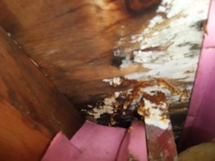
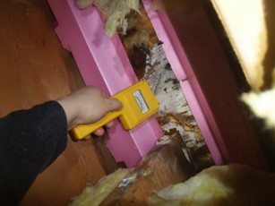
Similarly, if you have white and brown slimy mold growing on your roof sheathing, you know that you have a big problem (Figure 22); again, the moisture meter was pegged (Figure 23). Although the moisture problem seems obvious, taking these measurements can let you know—for instance—that the roof is dry in the summer, but obviously wetted at other times of year.
|
Figure 22: Poorly vented cathedral roof fungus |
Figure 23: Delmhorst meter at roof sheathing |
The Tramex meter is my go-to for any masonry measurements, but that raises a question: concrete can stay wet without a problem. We build foundations, outdoor bridges, and docks out of concrete—how wet is too wet?
My answer is less of an absolute number, and more of using that 0 to 100 relative scale to look for patterns. Is just part of the wall getting wet, and if so, why is it happening, and can we prevent it?
For example, in Figure 24, the homeowner complained about foundation moisture issues, as demonstrated by the interior paint/coating bubbling in spots. A map of the wall’s moisture (Figure 25) showed some pretty clear patterns: only the below-grade part of the wall was affected, and the worst problems were near the bottom of the wall and the corner. That’s all consistent with groundwater penetrating the below-grade wall, and possibly running down to the bottom via the hollow CMU block cores.
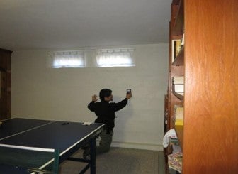
Figure 24: Tramex moisture meter measurement of CMU basement wall
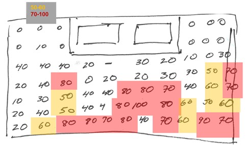
Figure 25: Moisture map of CMU basement wall
Lastly, watch out for any metal embedded in what you’re measuring with this meter—it will set off high moisture false alarms. For instance, metal drywall corner beads will show up as “wet” spots.
Case Studies: Slab Floor Moisture with Wood Sleepers
Another use for various moisture meters is investigations of slab moisture. Concrete stores an immense amount of water from the day it is cast and dries out slowly. If that moisture is dealt with improperly, you can run into problems.
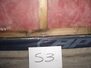
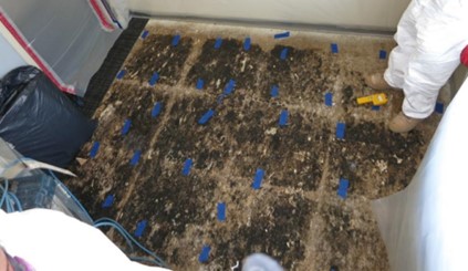
One example was an investigation of a 4 year old wood frame mixed use building (office and residential) in the Northeast. The work was prompted by severe subfloor rot at areas over a slab on grade. The finish floor was rubber-backed carpet tile, adhered to the Advantech OSB subfloor; removing the carpet tile revealed black staining at problem areas (Figure 26). The same subfloor and carpet tile were used over the basement, which had no moisture problems or black staining (Figure 27).
|
Figure 26: Subfloor discoloration under carpet tile at slab-on grade condition |
Figure 27: Subfloor intact (no discoloration) at basement condition |
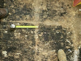
When the floor of an office was demolished, we found the black patterns exactly matched the carpet tile layout—you could make out every joint (Figure 28 and Figure 29).
|
Figure 28: Discoloration matches carpet tile patterns |
Figure 29: Less discoloration at seams |
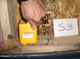
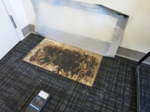
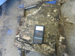
When they demolished the floor (Figure 30), we found extensive damage and high wood moisture contents in the subfloor and horizontal lumber sleepers on the slab (Figure 31). Typical subfloor MCs were in the 18-25% range; damage was visible on both top and bottom sides, but the bottom was wetter.
|
Figure 30: Disassembly of floor over slab |
Figure 31: Tramex measurement of subfloor |
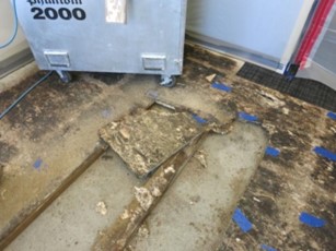
The problem was caused by moisture of construction in the concrete slab and the design of the sleeper and subfloor system. The rubber-backed carpet tiles are vapor impermeable (i.e., a “vapor barrier”), trapping moisture within the assembly. This moisture accumulated in the subfloor and sleepers, resulting in the rot damage. The “grid” pattern was caused by the small amount of drying available at the rubber carpet tile joints. The assembly was built contrary to the subfloor manufacturer’s directions, which call for a polyethylene vapor barrier on top of the slab, below the sleepers.
Our recommended remediation was to remove the sleeper and subfloor assembly, and rebuild with a layer that controls moisture emission from the slab. Epoxy paint on the slab was recommended to control moisture, while being unaffected by the wet slab.
Case Study: Cupping Flooring over Concrete Slabs
Another case study was a newly-built house with a strip wood floor on subflooring, sleepers, and a radiant floor concrete slab. As construction was wrapping up, the entire subfloor began to cup. Again, this was a slab moisture problem: in addition to construction moisture, the slab was loaded up by a rainy and snowy winter before the building was dried in. This problem occurred even though the slab had four months of drying.
A common test used by the flooring industry to tell whether a slab is “dry enough to floor over” is the calcium chloride “dome” test (ASTM F1869). It involves taping a plastic dome down to the floor, covering a cup of calcium chloride; the moisture weight gain of the adsorbent calcium chloride provides an indication of slab moisture emission. However, it can give erratic results: previous floor coverings and temperature differences can all swing the measurement.
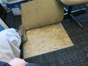
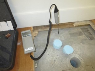
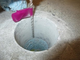
Much of the industry has switched to a measurement of the slab’s internal relative humidity, using a hole drilled into the slab (ASTM F2170). We did a quick field expedient version of this test at this project (Figure 32)—the full test involves leaving the probe in place for 72 hours. When we drilled down towards the bottom of the slab (Figure 33), we found there was still a major reservoir of moisture there—95% RH and still creeping upward after 15 minutes.
|
Figure 32: Slab internal T/RH measurement |
Figure 33: Drilled hole to lower part of slab |
To fix these slab problems, we have the choice of either drying the slab—which could involve waiting for a very long time—or containing the moisture in the slab, so it can’t damage anything else. My boss Joe talks about this problem—wood floors over concrete slabs—in this column. BSI-082: Walking the Plank
One option is to coat the topside of the slab with an epoxy coating, which can handle the slab moisture without “blowing off,” as shown in Figure 34.
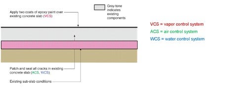
Figure 34: Insulated “wet” slab covered with epoxy paint for vapor control
Another solution is to build up the topside of the wet slab with an air gap membrane or “dimple mat,” insulation, and a “floating” subfloor (Figure 35). The air gap membrane functions as an air- and vapor barrier, and contains the moisture. As slab moisture evaporates into the air gap space, the air will become saturated/wet, which will stop evaporation from the slab when conditions come into equilibrium.
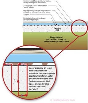
Figure 35: Topping slab with topside buildup of dimple mat, insulation, and subfloor
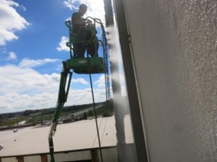
Water + Air (Window Testing)
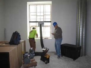
Air and water are combined in building performance when doing window water leakage testing. The test involves spraying the exterior of the window with water (Figure 36), while a clear sealed chamber is used to depressurize the window opening from the interior (Figure 37), simulating the effect of wind-driven rain. Officially, this is an ASTM E1105 test, which is part of an AAMA 502 test ("Voluntary Specification for Field Testing of Newly Installed Fenestration Products")—this work is done by testing companies specializing in this work. These tests are typically run as a building commissioning or quality control step in new commercial construction or renovations.
|
Figure 36: Window test spray rack in operation |
Figure 37: Window interior depressurization rig |

These tests can be pretty severe loadings: if a window passes, it is very unlikely to leak in service. To put it in context, a representative window test pressure might be 3.5 to 5 pounds per square foot (PSF), which is equivalent to 170 to 240 Pascals. When stagnation pressure is plotted against equivalent wind speed (Figure 38), you can see that it’s roughly equivalent to a constant 55 25-35 mph wind hitting the window. Continuous dumping rain with constant winds that high—not gusts—is a pretty severe and rare storm.
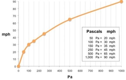
Figure 38: Stagnation pressure (Pascals) versus wind speed (mph) graph
Case Study: Window Leakage Diagnosis and Testing
Many leaky windows will let water in even without a pressure difference. But we can use the concepts above to simulate wind driven rain. Wind-driven rain can push water “uphill,” over slopes and dams that are intended to keep water out.
For example, we were asked to diagnose windows that leaked, but only when there was wind-driven rain coming from a certain direction at the site (Figure 39). The windows had been leaking since they were installed, with problems commonly showing up as drywall bubbling at the bottom corners of windows (Figure 40), where leakage would tend to run down.
|
Figure 39: Residences with window leak issues |
Figure 40: Damage at bottom window corners |
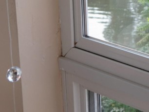
But drywall problems were also seen at the window jambs, at the mull joint between the upper and lower window units (Figure 41 and Figure 42). Mulled windows are notorious for being causes of water leaks.
|
Figure 41: Windows mulled together (upper/lower) |
Figure 42: Damage at jamb at mull joint |
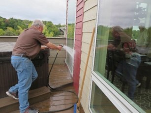
To simulate wind-driven rain, we sprayed the outside of the window with water (Figure 43), while depressurizing the building to -50 Pascals, equivalent to roughly a 20 mph wind (Figure 44). The goal of spraying is to create a “film” of water on the surface—not necessarily to “blast” it into the openings with force.
|
Figure 43: Water spray testing windows |
Figure 44: Building depressurization while spraying |
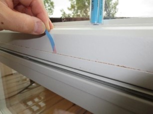
Within five minutes, we saw water coming in at the horizontal mull joint (Figure 45). We also demonstrated the leak with cobalt chloride water indicator paper strips (Figure 46): the color change is often useful to demonstrate wetting in pictures, where clear water might not be evident.
|
Figure 45: Water leakage coming in at mull joint |
Figure 46: Cobalt chloride water indicator paper |


Also, pushing on the vinyl extrusion at the bottom of the upper window made water seep out of the joint (Figure 47); this was also confirmed with water indicator paper inserted into the joint (Figure 48). After taking a closer look at the window design, this water was on the “dry side” of the window (inboard of the gaskets)—water getting back here is an indication that things had failed.
|
Figure 47: Water pushing on vinyl joint |
Figure 48: Water indicator paper to probe joint |
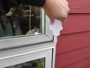
Another handy tool is a water squirt bottle: it can be used to inject water right into a suspect joint (Figure 49), rather than trying to cover the entire window with water and hoping to hit the right spot. We suspected that when rain was pushed through the outboard ‘fin’ gasket, it would leak right in—again, confirmed with water indicator paper (Figure 50).
|
Figure 49: Water squirt bottle injecting water |
Figure 50: Water leakage due to injection |
Water + Heat (Tracing Water)
We can also use infrared thermography (i.e., an infrared camera) to look for water leaks; we touched on this topic briefly in How to Look at a House like a Building Scientist (Part 2: Heat). Water leaks often show up as cooler areas, both from cold water temperatures (e.g., rainwater), the cooling effect of evaporating water, and/or water’s thermal mass. An infrared camera made the roof/ceiling leak in Figure 51 obvious; the cause was a poor flashing connection between the window sill pan flashing and the EPDM roof membrane.
|
|
|
|
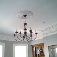
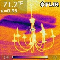
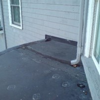
Figure 51: Water leakage at roof/ceiling insulated with open cell spray foam; EPDM roof-to-wall joint
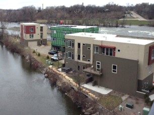
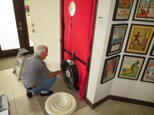
Case Study: Balcony with Glass Railing Water Visualization
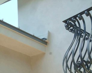
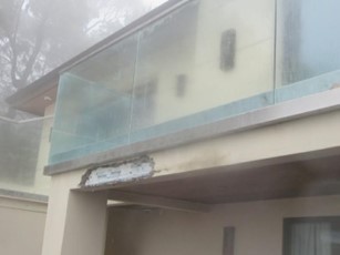
As a final case study, we were called out to the West Coast to look at a balcony railing detail that has resulted in dripping, staining, and cracks in the stucco wall below (Figure 52 and Figure 53).
|
Figure 52: Balcony with glass railing |
Figure 53: Leakage into stucco soffit below |
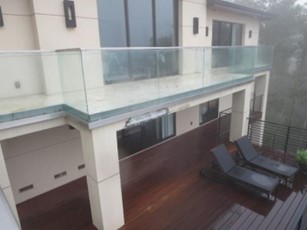
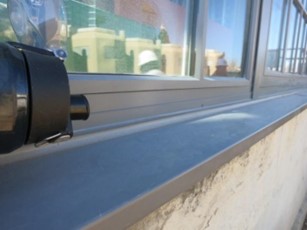
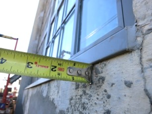
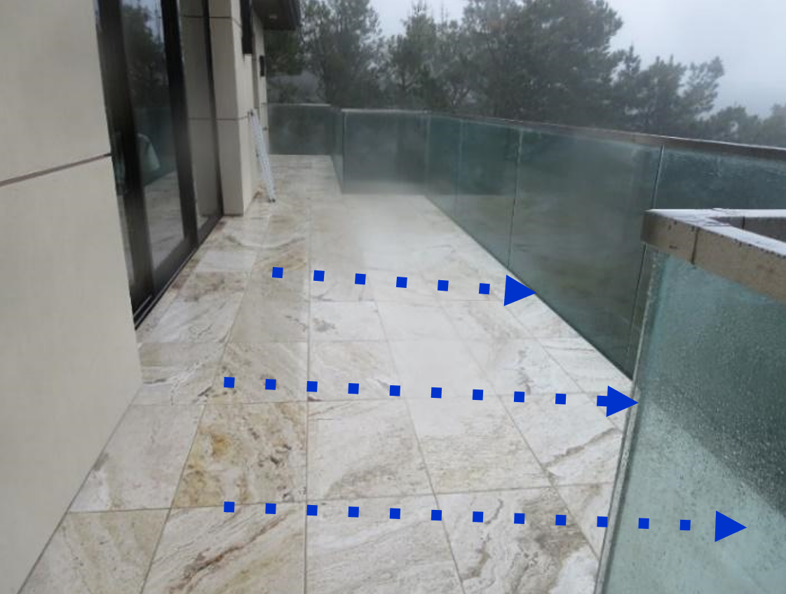
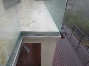
The balconies are sloped to drain water off the edge (Figure 54), and the glass railings are attached at their base to the vertical surface of the wall, with a recess at the balcony perimeter (Figure 55). I know—it’s a difficult-to-clean gutter designed to fill with crud—but I didn’t design it.
Based on the damage patterns, it soon became clear that the problem areas were not draining water properly: it was damming up and getting into the stucco, rather than dripping freely to the deck below.
|
Figure 54: Water drains off face of balcony |
Figure 55: Glass railing connection condition |
As you can tell from these pictures, I was on site on a dreary, cold, and drizzly day—which makes it very difficult to demonstrate water flow patterns using an infrared camera—everything is already cold and wet. I could have run out to the supermarket to grab some food coloring, but I don’t think the client would have appreciated purple stains all over his mansion.
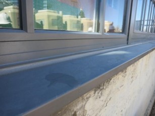
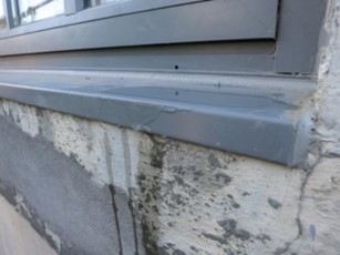
The answer: fill up my squirt bottle with hot water from the sink, and let it dribble over the edge. Parts of the balcony allowed free drainage (Figure 56). The patterns also show that the water “wraps” around the underside of the soffit rather than dripping free. But at other parts of the balcony, no water came out—it was all dammed up by the glass railing detail, causing the stucco damage (Figure 57).
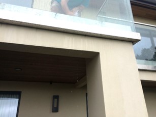
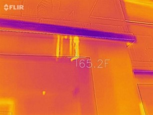
Figure 56: Visual and infrared image of correctly-draining glass railing detail (drainage gap)
|
|
|
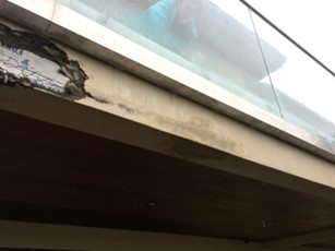
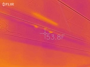
Figure 57: Visual and infrared image of incorrectly-draining glass railing detail (no drainage gap)