This two-story slab-on-grade enclosure is designed for Orlando, FL (Hot-Humid Climate). The roof features Structural Insulated Panels (SIPs) and a standing seam metal roof. The walls consist of 6” nominal SIPs with fiber cement and brick veneer cladding. The slab is left uninsulated.
Enclosure Design
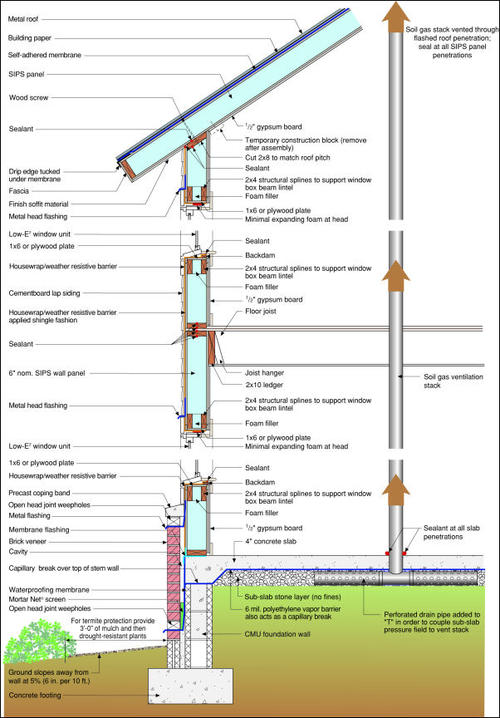
Construction Recommendations
- Foundation: Block stem wall with slab
- Wall type: SIPS
- Wall cladding: Cement board siding/brick veneer
- Roof: Conditioned attic / cathedral ceilings
- Roof cladding: Metal roof
Building Science Details
|
|
|
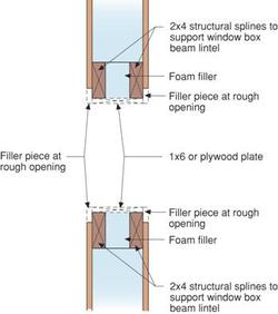
Figure 3: Load bearing window jamb assembly |
- Air sealing details at transitions- Air sealing is important at assembly transitions such as top-of-wall/roof assembly junctions, SIPS panel joints, and between attached garages and living spaces.
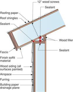
- Top-of-wall/roof assembly junction – Air barrier continuity can be provided at this junction if sealant is used on the top and bottom of the top plate. See Figure 1 for an alternative roof framing option using SIPS panels.
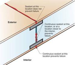
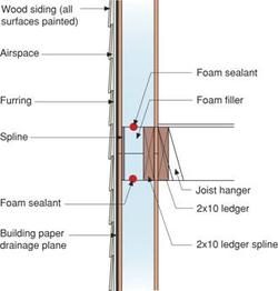
- SIPS panel joints – Air barrier continuity can be provided at SIPS panel joints with a continuous bead of sealant between foam sections and a continuous bead of sealant between the plywood or OSB skin panels on the interior. See Figure 2a for details. See Figure 2b for an alternative above grade wall spline detail. Also note on the cross section the wall/floor air sealing detail between the first and second floors.
- Attached garages – the building enclosure surfaces shared between conditioned space and an unconditioned garage must have a continuous air barrier.
Drying mechanisms – In any climate, vapor control is based on the relationships among the following: the permeability of wall components, the type of cladding (reservoir or non-reservoir), the presence/lack/nature of an air space, and the magnitude/duration of the vapor drive (based on the relationship between the exterior and interior moisture content and temperature differences). The type of sheathing and housewrap used in any wall assembly must be based on an understanding of these inter-relationships. See “Insulations, Sheathings, and Vapor Diffusion Retarders” for more information.
In both the first and second story wall assemblies, drying can occur to the exterior and the interior as long as permeable latex paints are used.Drainage plane, air barrier, and vapor control – The primary drainage plane behind both the cement board and the brick veneer is the housewrap/weather resistant barrier (WRB) over the SIPS panel and the waterproofing membrane over the slab and stem wall. Flashing details at penetrations must reflect this difference.
The housewrap/weather resistant barrier (WRB) is an important “back-up” protection against liquid water penetration into the SIPS panels. On first and second floor, the air barrier is the SIPS panel. Control of moisture drive from the outside in is accomplished by the relative impermeability of the SIPS panel.
The roofing paper underneath the standing seam metal roof has two functions. It serves as a slip surface for the roofing for expansion and contraction of the metal, and it serves as a secondary drainage plane for moisture that might condense on the underside of the metal roofing as the result of night-sky radiation and subsequent condensation.Window flashing – Window flashing details are wall assembly or cladding specific. See Figure 3 for a detail of a load bearing window jamb assembly.
Framing on slabs - Installing a capillary break between the sill plate and a concrete slab on all walls—exterior, interior, partition—is good practice. A closed cell foam sill sealer or gasket works well. Alternatively, a strip of sheet polyethylene can be used. This isolates the framing from any source of moisture that may be either in or on the concrete slab (and using sill sealer on all walls maintains wall height exactly the same).
Soil gas ventilation – The sub-slab to roof vent system handles conditions that are difficult if not impossible to assess prior to completion of the structure— confined concentrations of air-borne radon, soil treatments (termiticides, pesticides) methane, etc. The cost of this "ounce" of prevention is well balanced against the cost of the "pound" of cure. Note that this system is a passive system that can easily be converted to an active ventilation system by installing an in-line fan into the stack in the attic.
Thermal barrier – The foam sandwiched between the plywood skins of the SIPS panels on the walls and roof is the thermal barrier. It should be noted that in this climate, moisture control does not require specific levels of insulation; but, it does require joints between panels be sealed to control air transported moisture. Inside/outside temperature differences do not require cavity-warming exterior rigid insulation to control wintertime condensing surface temperatures.
Sub-slab stone bed - The four-inch deep 3/4" stone bed functions as a granular capillary break, a drainage pad, and a sub-slab air pressure field extender for the soil gas ventilation system. The sub-slab stone bed is a practical method for venting soil gas should be necessary.
Climate Specific Details
Termite management - In hot-humid climates, termites are best managed with a three-pronged approach that deals with the three things termites need - cover from sunlight, moisture, and food (wood or paper):
- Reduced cover - Keep plantings 3 feet away from the building perimeter, thin the ground cover (wood mulch or pea stone) to no more than two inches depth for the first 18 inches around the building, and maintain the termite inspection zone on the exterior of the foundation above grade.
- Control moisture - Maintain slope away from building as shown, carry roof load of water at least three feet away from building, and make sure that irrigation is directed away from the building.
- Chemical treatment - Use an environmentally-appropriate soil treatment (such as Termidor®) and a building materials treatment (such as Bora-Care®) for termite-prone near-grade wood materials.
- Inter-relationship of first three points – Since a builder and a homeowner’s ability to employ or stick to each of the three strategies above will vary, make sure that an inability to fully employ one strategy is compensated for by complete rigor by the others. For example, if for some reason, chemical treatment of soil or building materials is not an option, then complete rigor in controlling moisture and ground cover must be maintained.
Conditioned attics – As an alternative to cathedral ceilings, a conditioned attic may be constructed to house the HVAC equipment or be used as additional living space. This assembly may require discussion with local building code official.
- Mechanical systems - The key elements of a system for this climate are:
- Sealed combustion gas furnace - for energy efficiency and health/safety with the unit inside conditioned space.
- Minimum 12 SEER AC unit - for energy efficient management of sensible load.
- Central-fan-integrated supply ventilation - this system is simple, effective, and economical. It provides fresh, filtered, outside air in a controlled amount using the existing HVAC delivery system for even distribution and mixing. Set-up intermittent central-fan-integrated supply, designed to ASHRAE 62.2P rate, with fan cycling control set to operate the central air handler as much as 33% of the time, but not less than 25% of the time, occurring within at least every three hours to provide ventilation air distribution and whole-house averaging of air quality and comfort conditions ($125 to $150). Include a normally closed motorized damper in the outside air duct with the AirCycler™ FRV control (+$50 to $60). See “Air Distribution Fan And Outside Air Damper Recycling Control" for more detailed information.
- Supplemental dehumidification - all homes in this climate call for supplemental dehumidification; the reduced sensible load of high performance homes reduces the dehumidification the AC unit provides, extends shoulder seasons, and raises the impact of occupant-generated moisture.
There are a number of different ways to accomplish supplemental dehumidification with varying costs and performance advantages (For a detailed discussion of supplemental dehumidification, see Air Conditioning.). Described below is one low-cost yet effective approach and one more costly but higher performance/systems-engineered approach:
Ducted stand-alone dehumidifier: This system is a "site-constructed" and consists of an off-the-shelf standard dehumidifier ducted in the attic and controlled by a dehumidistat located in the living space. This arrangement of individual components has proven to be an effective and economical system for the production home building setting. The installed cost ranges from approximately $350 to $550. The system is comprised of any Energy Star dehumidifier that uses a blower wheel instead of a paddle fan to move air past the coil (dehumidifier located in attic in an insulated enclosure and ducted to living space), Honeywell dehumidistat model H8808C located in living space and Honeywell switching relay (with transformer) model RA89A 1074.
Note: The following manufacturers make Energy Star-qualified blower wheel stand-alone dehumidifiers:
- LG Electronics (all models):
- Haier America (all models):
- Heat Controller (all BHD models use a turbo-impeller with turned blades):
- Or you can check the EPA Energy Star website for dehumidifiers from these manufacturers
Aprilaire 1700: This is a truly engineered, coherently manufactured, supplemental dehumidification system with built-in air filtration, ducted design, and a controls package that integrates central blower cycling for distribution, dehumidification and intermittent introduction of outside air ventilation. The system is also designed for flexibility-it can be connected to the conditioned space directly or to the central air distribution system in a number of configurations. It's also compact and lightweight enough to be set on or hung from most framing. The product cost for this system is currently about $1,100. For more information, see: http://aprilaire.com.
For more information on other high performance supplemental dehumidification systems, see: http://www.thermastor.com.
Ducts in conditioned space - The preferred method for keeping HVAC ducts and mechanical equipment inside conditioned space is moving them down from the attic. In this building profile, a conditioned attic can be used for HVAC ducts and equipment. In no case should HVAC ducts be placed within exterior wall assemblies-this is not part of what is meant by ducts in conditioned space. A vented attic assembly may be used in this climate as long as the ceiling plane is air tight and no ductwork or air handling equipment is located in the attic.
Transfer grilles – Single air returns require transfer grilles to provide return pathways that prevent pressurization of bedrooms. Appropriate sizing for ducts, including these pressure relief methods, can be found in the Cooling System Sizing Pro.
Water heater - any type of gas water heater (in terms of venting) works if the water heater is located in the garage. If the water heater is located inside conditioned space, then it must be a gas power vented or power-direct vented unit, or an electric water heater.
Field Experience Notes
Air sealing and telegraphing of panel joints – An increase in moisture content can occur due to air leakage through panel joints. Air transported moisture will migrate to the cold side of the panel causing the cold side of the panel to expand relative to the warm side. See Figure 2a for air sealing locations between panels.
Roofing - Light-colored standing seam metal roofs yield the best cooling load reduction of any roof claddings. We recommend a metal roof that meets the EPA/DOE Energy Star qualifications.
HVAC commissioning – The most efficient equipment means little if the system is not set up and started up properly. Follow high performance start-up procedures.
Material compatibility and substitutions
Exterior sheathing/building "paper" - A variety of building papers or housewraps installed shingle fashion can act as the drainage plane in this assembly. While drying to the exterior is not the primary mechanism in this climate, the combinations of building papers and exterior sheathings in this assembly (and their relative permeabilities) promote intermittent drying in this direction.
Flooring - Many finished flooring materials — either because of their impermeability (sheet vinyl, for example) or sensitivity to moisture (wood strip flooring, for example) — should only be installed over a slab with a low w/c ratio (≈0.45 or less) or a slab allowed to dry (0.3 grams/24hrs/ft2) prior to installation of flooring. In general, sheet vinyl flooring should be avoided.
Sub-slab sand layers - A sand layer under the slab (to prevent differential drying and cracking) should never be placed between a vapor barrier and a concrete slab. Cast the concrete directly on top of the vapor barrier. This problem is better handled with a low w/c ratio (≈0.45 or less) and wetted burlap covering during initial curing.
Latex paint - The substitution of low permeability finishes (vinyl wall paper, oil-based paints) for latex paint is strongly discouraged because of reduced drying potential. (Note that there are latex paints with very low vapor permeabilities, but they are generally clearly labeled as such.)
Gypsum wallboard - Areas of potentially high moisture, such as bathrooms, laundry rooms, and kitchens are excellent candidates for non-paper faced wallboard systems (e.g. James Hardie’s Hardibacker®, GP’s DensArmor®, USG’s Fiberock®). In addition, paper-faced gypsum board should never be used as interior sheathing or backer for tub or shower surrounds where ceramic tile or marble (any material with joints or grout lines) is used as the finish.

