…articulaciones* y esquinas y penetraciones...much more stylish…much more interesting than English. The battle to control water entry is won at building joints and corners[1] not so much at penetrations, but pointing that out apparently is boring and unfashionable. So we are going Castilian to try to make joints and corners sexy and exotic and penetrations passe in the hope of addressing water control.
The first place to start is that buildings move… how is that for sexy and exotic? They move a lot. Most of us understand the dead load part and the wind load part and the snow load part and the live load part and the traffic part and the creep part[2]. Some of us understand the thermal part and the hygric part. It is not possible to have a building that does not move.
Since buildings move everything attached to them also moves…especially the skin. We are going to arbitrarily and capriciously define the skin as the cladding and say that the cladding is attached to structural frame. We have also pointed out over and over and over that claddings leak rainwater and because of that the claddings need help on the rain part.
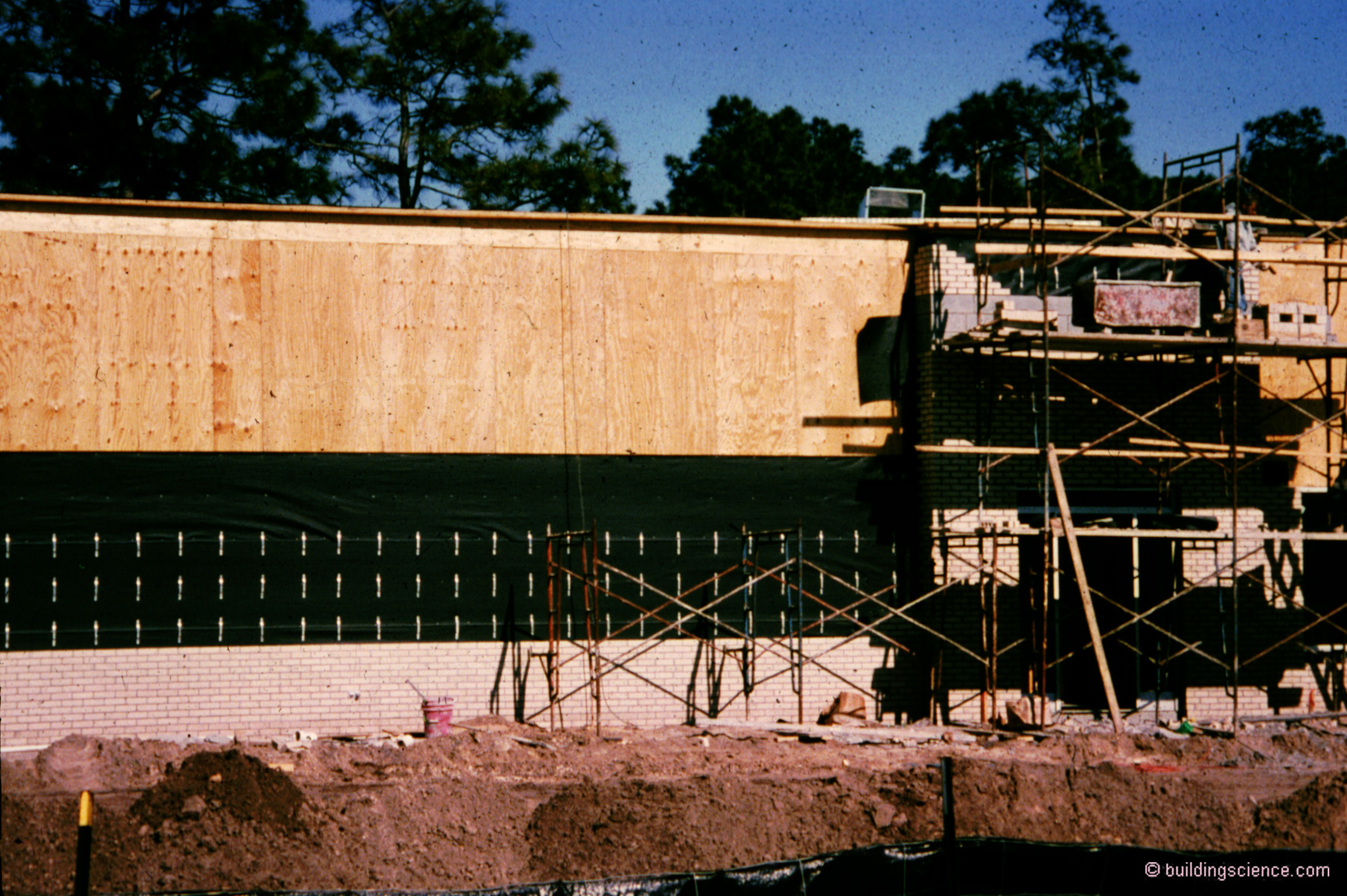
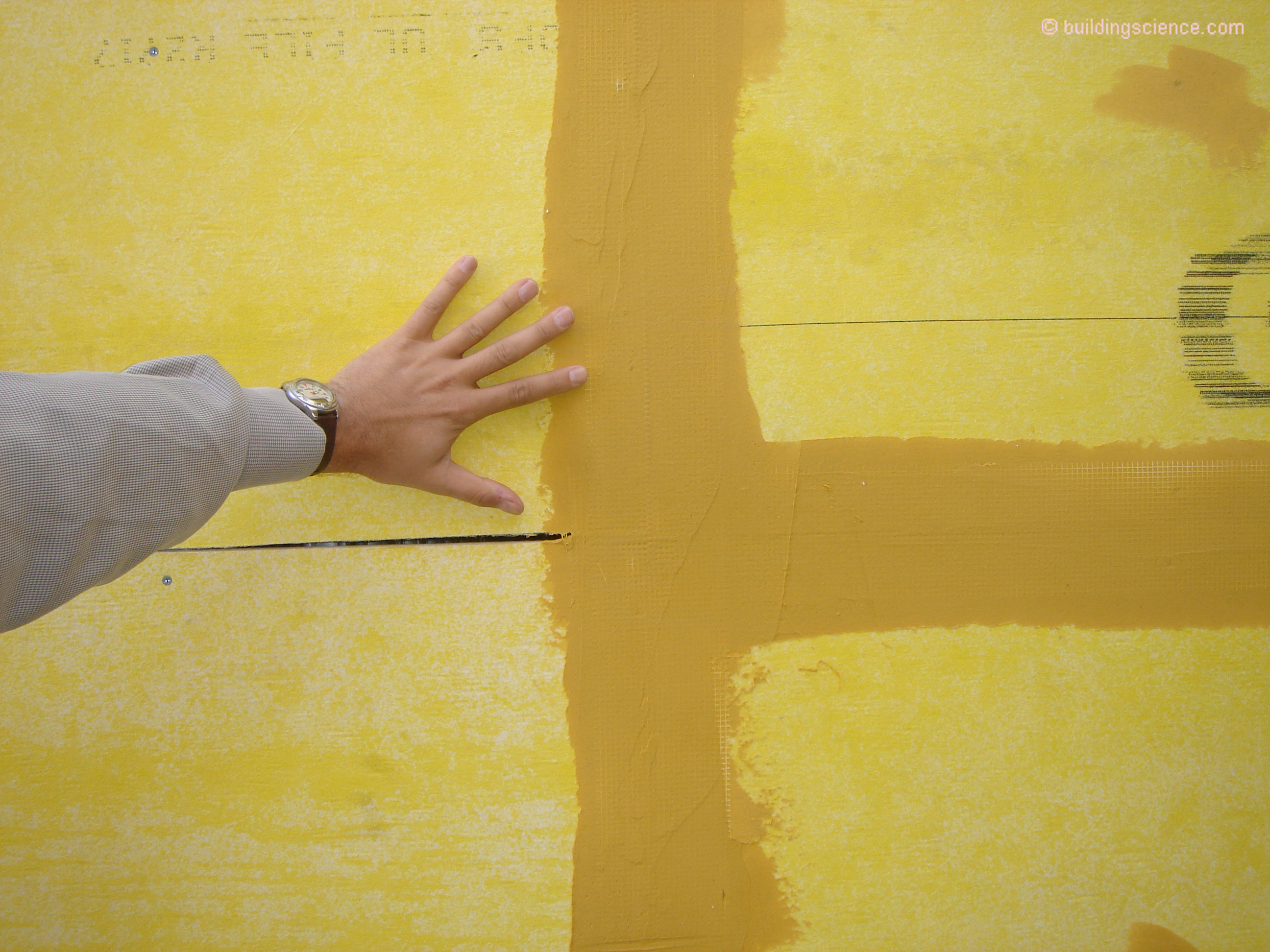
To help the claddings on the rain leak part most of us install a water control layer behind them. So far so good. Nothing new here yet. The new part is what is going on with the water control layer. Most of us now have the water control layer also be an air control layer. We combine the functions of water control and air control and use materials and systems that are relatively new and that makes lots of folks nervous. One trend is to sheet goods covered with spray applied liquid membranes (Photograph 1), brush applied liquid membranes (Photograph 2) and sheet goods with integral water and air control layers (Photograph 3). Note the word “sheet goods”. Sheet goods get put together with joints and inside and outside corners. How we deal with the joints and the inside and outside corners[3] is the trick (Photograph 4).
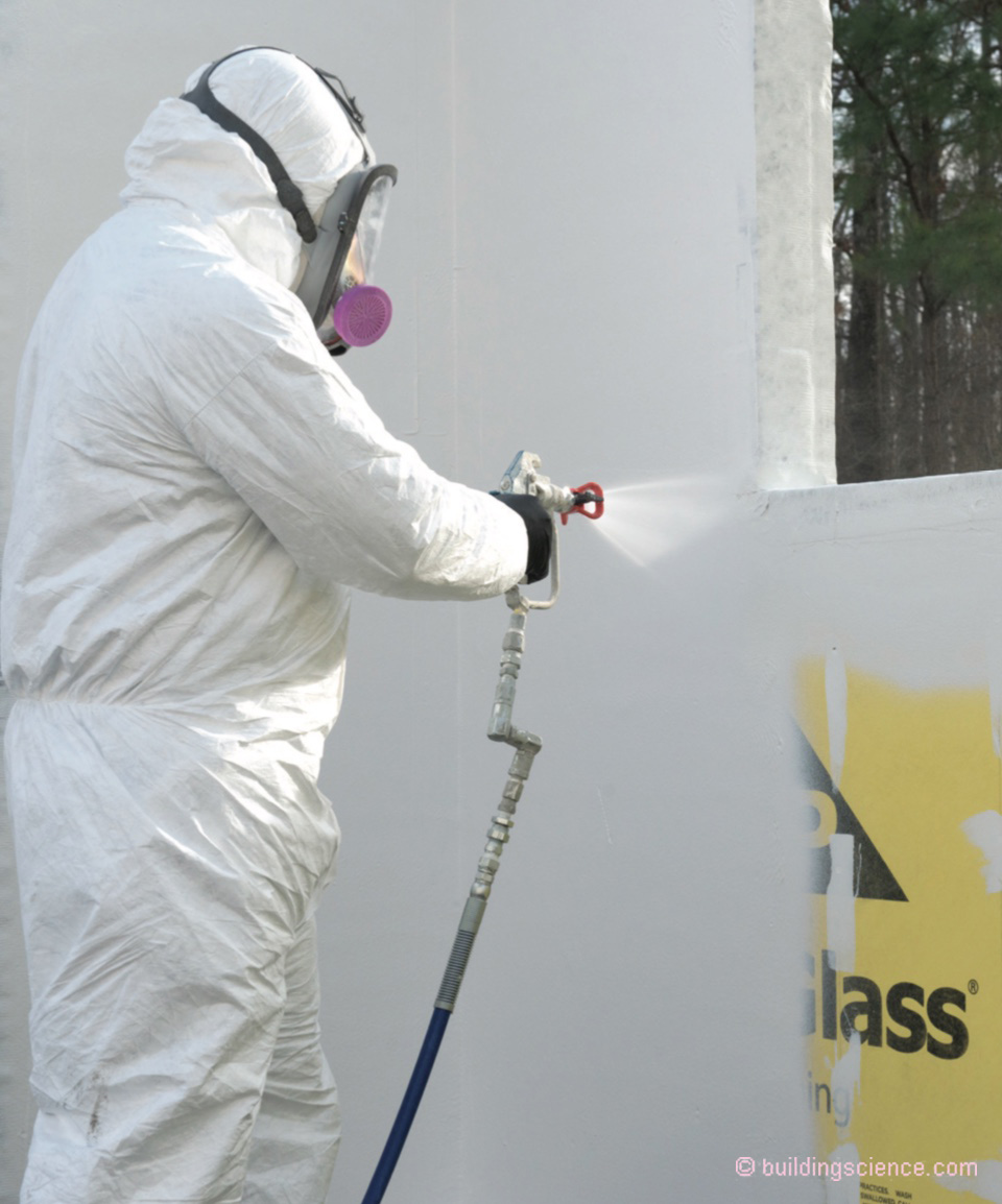
Photograph 1: New Systems - The trend is to sheet goods covered with spray applied liquid membranes. Note the word “sheet goods”.

Photograph 2: More New Systems – Gypsum board sheets covered with trowel applied membrane.

Photograph 3: Still More New Systems - Sheet goods with integral water and air control layers.

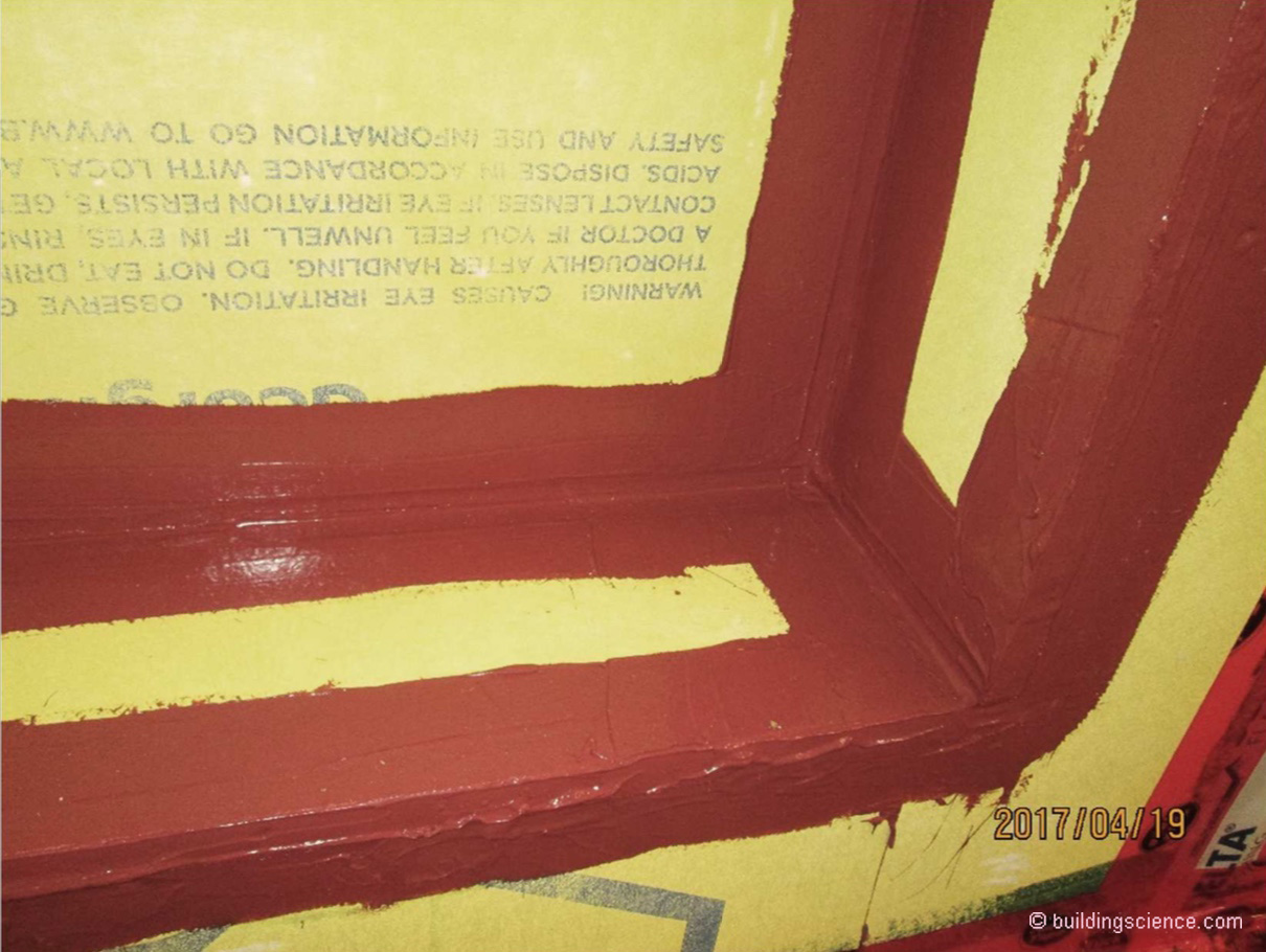
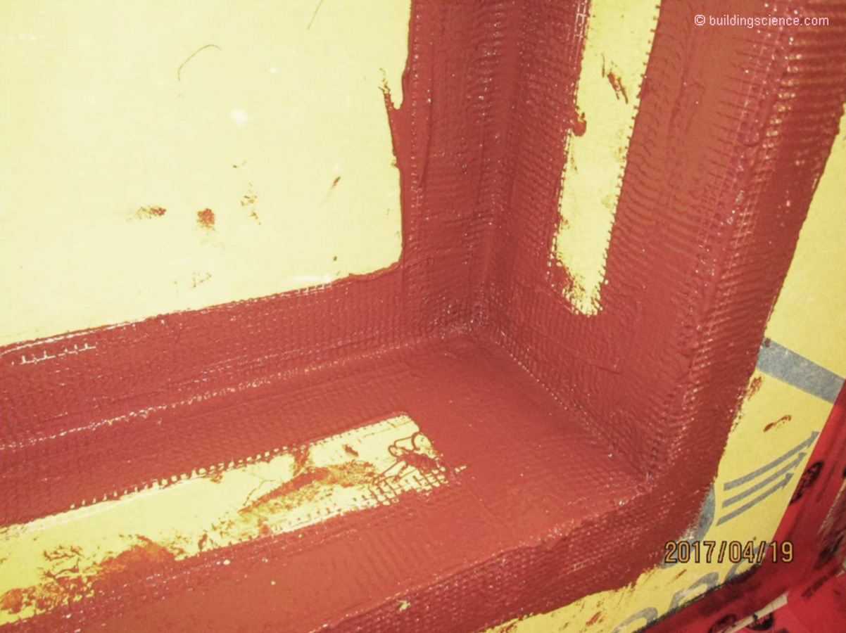
Photograph 4: Window Opening – Lots of joints and inside and outside corners. How we deal with the joints and the inside and outside corners is the trick. Note the “filet” sealant in the “end dam” and “back dam” under the liquid applied membrane.
Apparently a point missed by folks is that we installed asphalt impregnated felt, Type D coated building papers and building wraps by nailing and stapling them and then we nailed and screwed cladding systems through them and did nothing special at the resulting penetrations and the world did not come to an end (Photograph 5)….but when we reverse lapped them and didn’t double cover the big corners and didn’t integrate them with windows, doors and glazing systems that were “innie, outie and tweeny”[4] and didn’t leave a gap between them and the cladding systems to control hydrostatic pressure and capillarity the world did come to an end.
Photograph 5: Old School - Apparently a point missed by folks is that we installed asphalt impregnated felt, Type D coated building papers and building wraps by nailing and stapling them and then we nailed and screwed cladding systems through them and did nothing special at the resulting penetrations and the world did not come to an end….
Back to movement. Joints and inside and outside corners open up and close up all the time. The gaps get bigger and the gaps get smaller. Let me repeat the point here…they don’t just open up…they go back and forth. The water control layer we cover them with…the liquid applied membranes that are spray applied, brush applied, trowel applied, or whatever, need to be elastic. Think rubber band. There is elongation and recovery. There is cycling. There is fatigue. There is aging.
There is more. There always is. The geometry of the joint and corner matters. Both the material properties of the joint and corner treatment and the geometry of the joint and corner matter.
With a “difficult” joint and corner the material properties of the liquid applied membrane are a big deal. With an “easy” joint and corner the liquid applied membrane is stressed less. Not too many liquid applied membranes have the material properties to handle “difficult” joints. But with the field experience over the past two decades with liquid applied membranes we can turn “difficult” joints in to “easier” joints. The best combination of course is combining a high performance liquid applied membrane over a joint that has been made less stressful.
Yup, there is more. Exposure. A two-story house with overhangs in Salt Lake City does not have much of an exposure compared to a 10 story mixed use building in Seattle. “Difficult” joints and corners in Salt Lake City low rise buildings have not been proven to be “difficult”. You don’t have to do much. But “difficult” joints and corners on high rise buildings in Seattle have been proven to be “difficult”. What is high rise? Ah, to this old guy it is anything over two to three stories.
So now we have to add exposure to the material properties of the joint and corner treatment and the geometry of the joint and corner. Note that exposure is fundamental to the material choice and detailing. This is a really big deal and fundamental to all buildings and all systems.
What is a “difficult” joint? Easy, a “butt” joint with nothing in the “butt”. Two pieces of gypsum sheathing or plywood sheathing or oriented strand board (OSB) sheathing butted together. Applying a liquid applied membrane over this type of joint is easy installation wise but as the joint opens and closes because everything moves all the time the liquid applied membrane is stressed. Recall elongation and recovery. So how to reduce the stress on the liquid applied membrane? Easy. Fill the joint with a sealant. Big improvement in performance. This works big time in corners. With inside corners a “filet” bead yields a nice curve rather than sharp change in direction (Photograph 6). With outside corners we have more of a curve rather than a sharp change in direction (Photograph 7).
Photograph 6: Stress Reduction - So how to reduce the stress on the liquid applied membrane? Easy. Fill the joint with a sealant. Big improvement in performance. This works big time in corners. With inside corners a “filet” bead yields a nice curve rather than sharp change in direction.
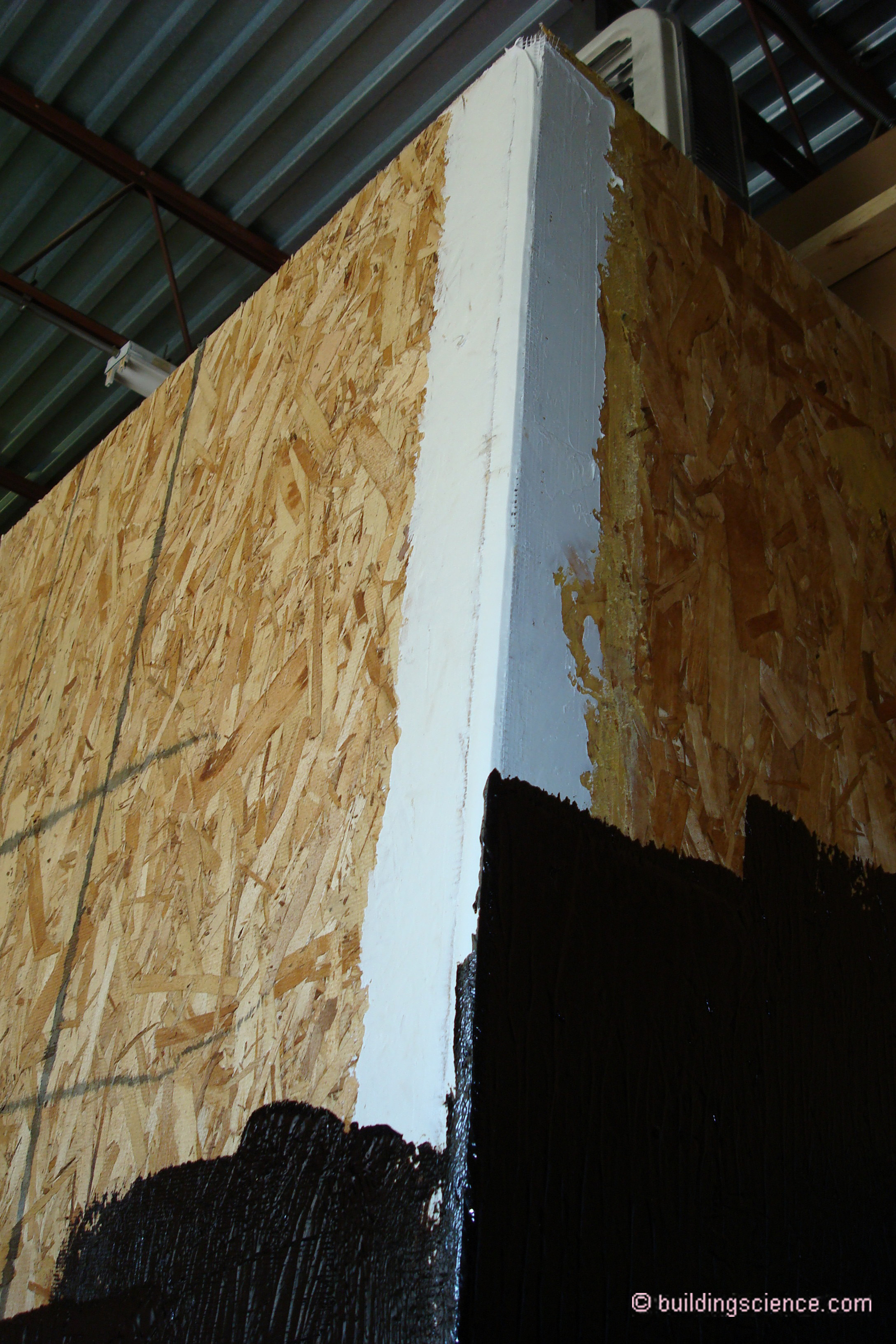
Photograph 7: More Stress Reduction - With outside corners we have more of a curve rather than a sharp change in direction.
Can we do more? Yes, of course. Reinforce the liquid applied membrane with mesh reinforcing (Photograph 8 and Photograph 9). However, adding mesh is a double-edged sword: it makes the joint stronger, but also stiffer, so stiff it can’t handle the movement anymore. The primary reason for the mesh (big insight[5]) in liquid membranes is to guarantee a minimum coating thickness. A wish list item is someone making a flexible and cheap mesh that guarantees thickness.
Photograph 8: Reinforced Joint - Liquid applied membrane reinforced with mesh.
Photograph 9: Modified Reinforced Joint – No sealing filling the joint…only mesh reinforcing.
Here are a bunch of general recommendations. I have divided up exposure into three levels in an arbitrary manner. You folks are going to have to make your own judgement on exposure. What follows is my best judgement at this point in time….and it applies to all joints with all systems…liquid applied membranes and sheet goods with integral water and air control layers:
Level One Exposure - For low exposure joints and corners a good liquid applied membrane does the trick.(low rise buildings where it rains less than 20 inches of rain per year).
Level Two Exposure - For medium exposure joints and corners fill the joints and corners with sealant and add the liquid applied membrane. Make the liquid applied membrane layer at least 4 inches wide….that requires more liquid and gets you a thicker membrane layer at the joint (low rise buildings where it rains more than 20 inches of rain per year and multistory buildings where it rains less than 20 inches of rain per year. I view all window and door openings…all punched openings as medium exposure joints and corners as a minimum regardless of rain exposure so punched openings in low rise buildings where it rains less than 20 inches of rain per year should have their joints filled).
Level Three Exposure - For high exposure joints and corners fill the joints and corners with sealant and reinforce the liquid applied membrane with mesh reinforcing. (multistory buildings where it rains more than 20 inches of rain per year).
Is there more? Yes, of course there is more. There should always, always, always be an air gap between the outside surface (“the wet surface”) of the water control layer and the cladding. Where a continuous non absorptive insulation is installed between the water control layer and the cladding an air gap should be provided at both the outside surface of the water control layer and directly behind the cladding[6]. The gap between the continuous non absorptive insulation and the water control layer does not need to be very large…continuous gaps as small as 1/32 of an inch have been shown to work effectively to control hydrostatic pressure, capillary and to promote drying. This gap should be limited in size as it adversely affects the thermal performance of the continuous non absorptive insulation. When this air gap exceeds ¼ inch expect a 5 to 10 percent reduction in the thermal resistance of the continuous non absorptive insulation layer.
This now leads us to screw holes for cladding attachment and screw holes for continuous exterior insulation attachment and screw holes for attachment of the sheathing itself. These are tiny and inconsequential. Yeah, but there are lot of them. Doesn’t matter. They can be ignored….except when they can’t be ignored.
Paraphrasing Gertrude Stein…a hole is a hole is a hole…..doesn’t matter if it is a screw hole through OSB sheathing with an integral water control layer facing or a screw hole through a liquid applied membrane over gypsum sheathing or a screw hole through a liquid applied membrane over plywood sheathing or a screw hole through gypsum sheathing with an integral water control layer…the holes are all tiny and inconsequential…and…wait for it… they all leak a little bit when really stressed.
So when can they be ignored? When you have a back vented and drained cladding and the wall assembly is able to dry. Note that the wall assembly needs to be able to dry. Permeance matters. Thermal resistance of continuous insulation matters.
So when can they not be ignored? When you have claddings without a drainage gap coupled to walls with an interior vapor barrier? Danger. Stucco walls without a drainage gap constructed in cold climates with interior polyethylene vapor barriers have issues even with very tiny holes. But the moment you add the drainage gap and get rid of the interior vapor barrier (you need to add continuous exterior insulation to do this in cold climates[7]) the tiny holes become inconsequential…even where there are lots of them. Not a lot of rainwater enters and the small amount that does enter is easily able to dry both outwards and inwards. Note that this means no interior vinyl wallcoverings or interior alkyd or epoxy paint coatings.
But what if I don’t want to ignore them even if I can ignore them? What can I do? Ah, easy. Here are a bunch of things that should be obvious but are not always obvious. They come from “skunk works” testing (Photograph 10). They apply to all the various combinations and permutations of liquid applied membranes over all sheathing types – gypsum, plywood and OSB and they apply to all the sheathing types with integral water control layers – gypsum and OSB.
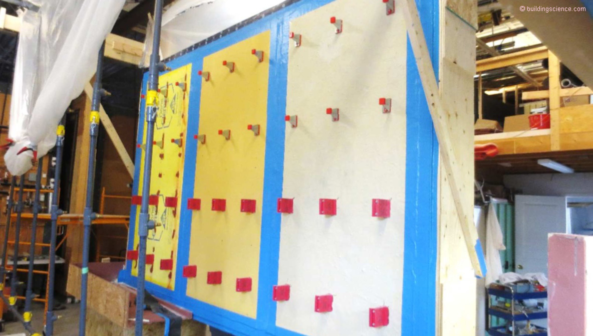
Photograph 10: Skunk Works – Secret unidentified secure location in Waterloo, Ontario where adults play with fasteners, clips and girts and spray water on them to create leaks…the term Hoser applies…Photograph courtesy of Chris Schumacher.
Screw heads, girts and any attachment plates need to be screwed tight to the sheathing. I repeat here…tight to the sheathing. OK, this is real obvious.
Coat the screw heads used to install the sheathing with a liquid applied membrane patch. OK, this is also real obvious.
Wet set cladding clips and brick ties – the clip and fastener is driven through a dab of liquid applied membrane. Should be obvious but is not always obvious. Easy to do.
Any more? Yes. This applies only to walls. Sloping walls are not walls. “If it is not vertical it is a roof…[8]”
So how do I deal with sloping walls? Easy, build them like roofs. See quote above.
For walls we have learned the following - the battle to control water entry is won at building joints and corners not so much atpenetrations… la batalla para controlar la entrada de agua se gana en la construcción de uniones y esquinas, no tanto en las penetraciones…
Sounds good in both English and Spanish…the same physics apply….
It also does not apply to closed cell spray polyurethane foam (SPF). We were here before (see Exterior Spray Foam, ASHRAE Journal, November 2010). The exterior surface of the SPF is the water control layer…so an additional gap is not required between the SPF and the sheathing it is applied over. Having noted that….also note that “punched openings” need transition elements between the SPF and the openings…
References:
Brown, J.B.; Thermodynamics of a Rubber Band; American Journal of Physics, 31:397, 1963.
Garden, G.K.; Rain Penetration and its Control, Canadian Building Digest 40, DBR/NRCC, April 1963.
Lstiburek, J.W. and Carmody, J.; Moisture Control Handbook, John Wiley & Sons, New York, NY, 1994.
Schumacher, C. and Straube, J.F.; Demonstrative Testing Program Report: Fluid Applied Membranes and Integral Systems, RDH Building Science Laboratories, August 2017.
Straube, J.F. and Burnett, E.F.; Building Science for Building Enclosures, Building Science Press, Westford, MA, 2005.
Wissink, K.S., Bashaw, L.K. and Ruggiero, S.S.; Comparative Analysis of Fluid-Applied Air Barrier Products; ASTM STP1549, West Conshohocken, PA, September 2014.
Young, P. H. and Meyer, B.; Critical Property Contrasts of Fluid-Applied Air and Water Barrier Membranes Used for Envelope: Chemistries, Performance and Durability; ASHRAE, BETEC, ORNL, DOE Thermal Performance of the Exterior Envelopes of Whole Buildings XIII International Conference, Clearwater Beach, FL, December 2016.
* We are talking real joints here….not “hierbas”…
[1] Hockey games are also won in “corners”…trying to appeal to my Canadian friends…
[2] Except in San Francisco and its leaning tower…ouch….they might want to talk to the folks in Pisa about designating it a World Heritage Site…when this gets settled…note the pun…everyone is going to know a great deal about friction piles and some Carole King lyrics….I feel the earth move under my feet….
[3] Besides the typical concept of building corners – big corners that everyone is familiar with - most people miss that window and door openings are nothing but a bunch of inside and outside corners…
[4] At “punched openings” windows and doors can be located inboard of the sheathing and frame, outboard of the sheathing and frame or in between….hence the phrase…also referred to as an architect genetic defect that requires origami flashing to treat…
[5] Thank you Professor Straube…see bibliography…
[6] This does not apply to external insulation finish systems (EIFS) where a gap between the EIFS exterior lamina (the “cladding”) and the continuous rigid insulation is not necessary. So little rainwater passes through EIFS only one air gap – the gap directly over the outside surface of the water control layer - is necessary. Also note that much of the industry experience relating to liquid applied membranes comes from the EIFS industry. Nice job EIFS folks.
[7] Yes, in cold climates we have more highly insulated and airtight walls so the drying potential is lower and therefore we can’t tolerate any leaks…and that is true when we only insulate within the stud cavities…when we insulate on the exterior of the sheathing and water control layer we elevate the cavity temperatures and increase the drying potential. See Confusion About Diffusion, ASHRAE Journal, December 2010.
[8] Famous saying of the legendary Werner Gumpertz.