Below grade water management is necessary for all below grade spaces. Yes, we were here before (BSI-125: Concrete Basement Foundations – July, 2021), but we covered only two approaches – the most common approaches – above the ground water table and the “draw down” approach. In real life, things can get more complicated. So here we are again.
The big, big obvious thing to appreciate - approaches are dependent on the location of the ground water table. And because Mother Nature likes to mess with us humans, the ground water table can vary with season.
Here is something not so obvious – approaches are not dependent on the foundation type (shallow: slab, mat/raft, spread/isolated footing, basement) (deep: pile, caisson, pier). For the record, “shallow” to foundation engineers and geotechnical engineers…means “not too deep – it includes typical residential basements…. Yes, there is more - approaches are also not dependent on climate zone.
Difficulties are common for urban sites due to the location of neighboring buildings, roadways and property lines that make it difficult to control surface water runoff and provide site drainage. Figure 1 illustrates the “classic” traditional method of providing site drainage – a method that is limited in urban sites. Although options for site drainage are limited in urban sites it is still important to utilize whatever site drainage is possible such as sloping sidewalks, driveways, patios, planters away from foundation perimeters.
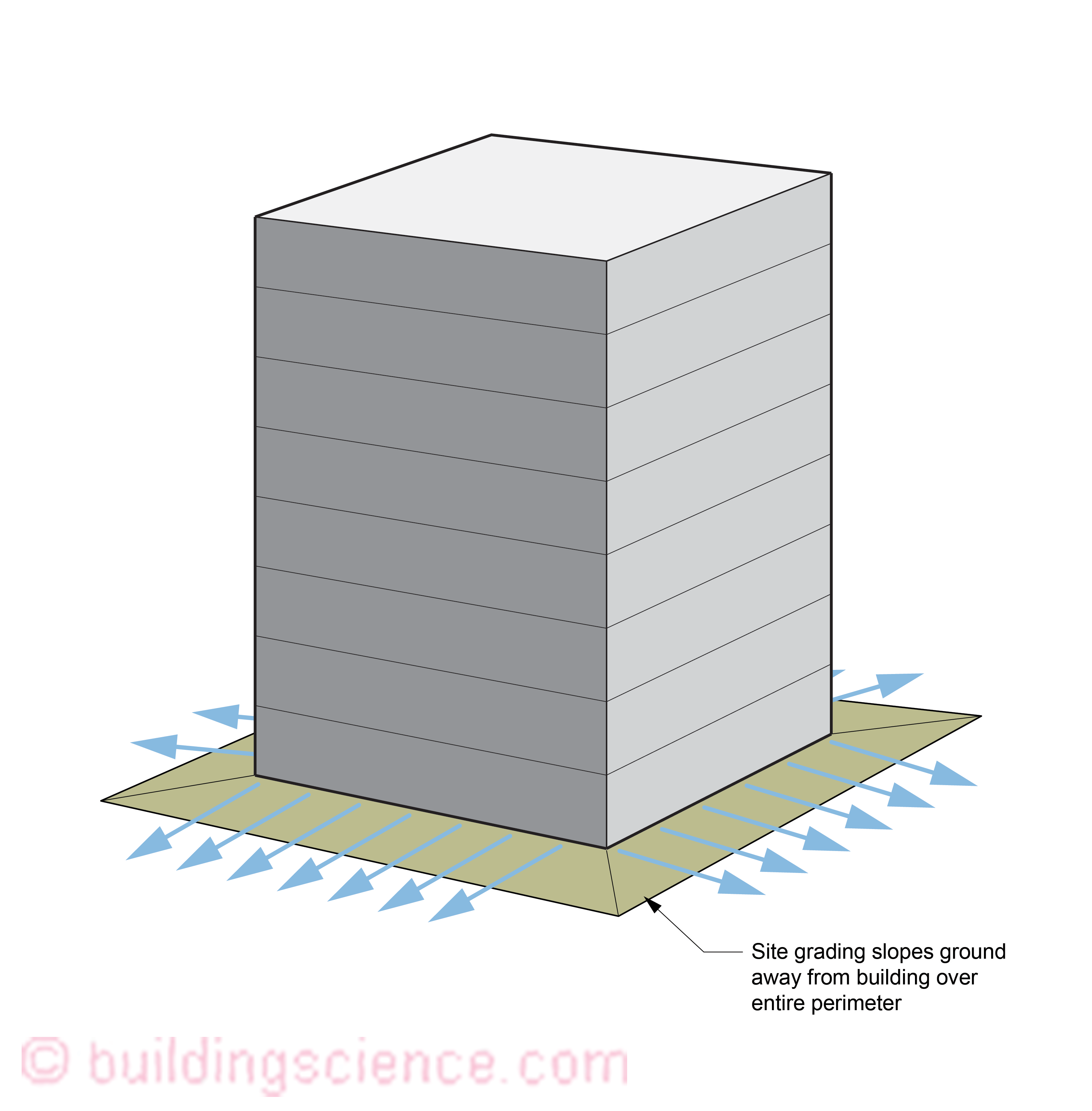
Figure 1: “Classic site drainage that is typically not possible in urban sites”
Where the foundation assemblies are located below the ground water table options are typically limited. The most common approaches are described below.
Above The Ground Water Table
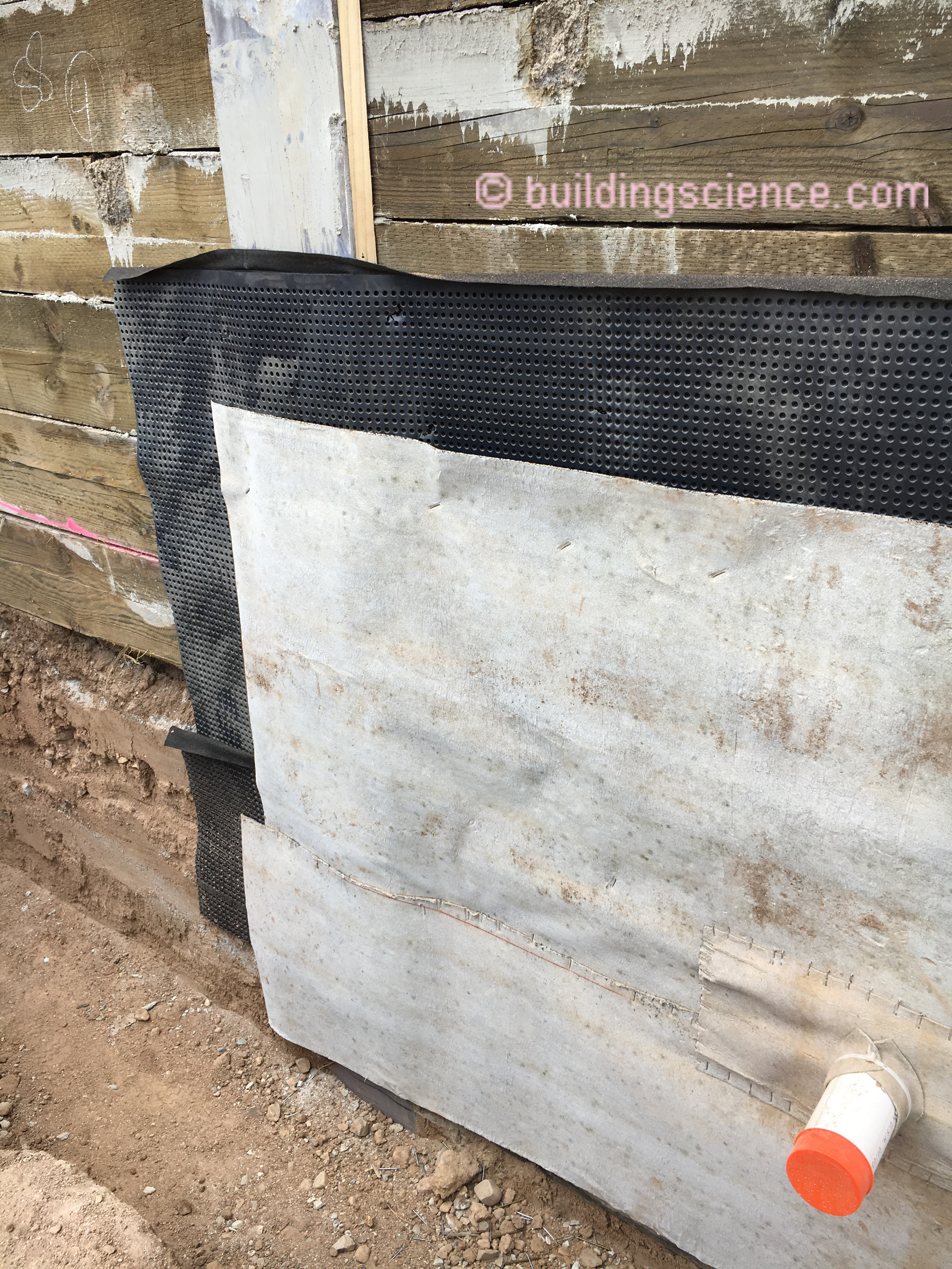
Figure 2 illustrates the approach recommended for addressing below grade water management where the foundation assembly is above the ground water table and access is available around the building perimeter. The waterproofing membrane is located on the exterior of the structure. The structure is typically concrete. A drainage layer is typically installed on the exterior of the waterproofing membrane (Photograph 1) and is connected to an exterior located perimeter drain. The perimeter drain is connected to a sump pit and sump pump. The sump is typically located internally in urban settings. Back up pumps and battery backup addressing power outages are recommended. Many drainage layer options are available such as drainage mats coupled with filter fabric, draining insulation boards, and traditional free draining backfill such as sand and gravel.
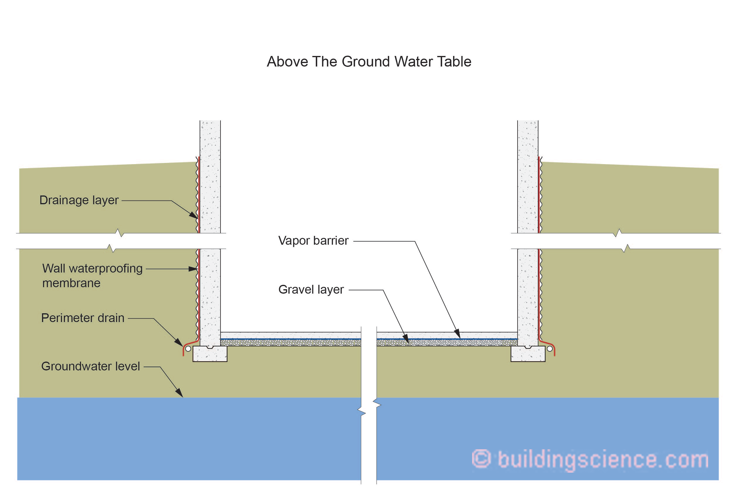
Figure 2: Below grade water management – foundation above ground water table
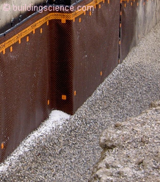
Photograph 1: Drainage layer located on exterior of the waterproofing
Draw Down
Figure 3 illustrates the “draw down” approach for addressing below grade water management where the foundation assembly is below the ground water table. Perimeter drainage of the soil adjacent the foundation assembly lowers the “local” ground water table adjacent the foundation. This approach is dependent on the rate at which water from soil not immediately adjacent to the foundation assembly moves/migrates/replaces the water removed by the perimeter foundation drainage. This approach is not appropriate where significant ground water is present and able to move laterally to the soil adjacent to the foundation. “Draw down” approaches require experienced civil engineering judgement and design.
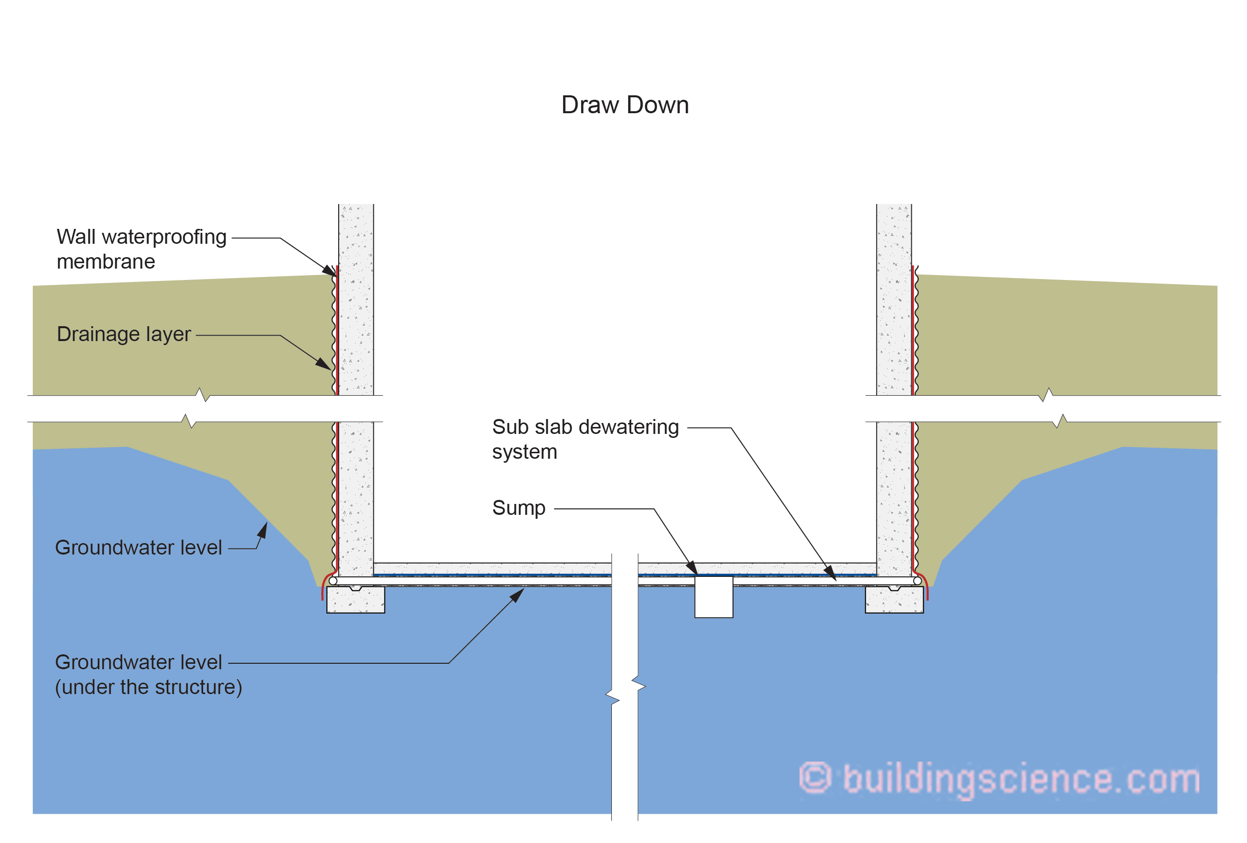
Figure 3: Below grade water management – foundation below ground water table – “draw down” approach
In this approach, as in the approach described in Figure 2, the waterproofing membrane is located on the exterior of the structure and the structure is typically concrete. A drainage layer is also installed on the exterior of the waterproofing membrane and is connected to an exterior located perimeter drain. The perimeter drain is connected to a sub slab dewatering system and sump pit and sump pump.
Perimeter Cut Off and Dewatering
Figure 4 illustrates the “perimeter cut off and dewatering” approach. In this approach a water cutoff system eliminates or slows the rate of water ingress into the excavation. The water cutoff systems are typically steel sheet piles extended down into an impermeable layer of soil. The waterproofing membrane is located between the steel sheet piles and the concrete foundation walls. A sub slab dewatering system lowers the groundwater level immediately under the structure. “Perimeter cut off and dewatering” approaches require experienced civil engineering judgement and design.
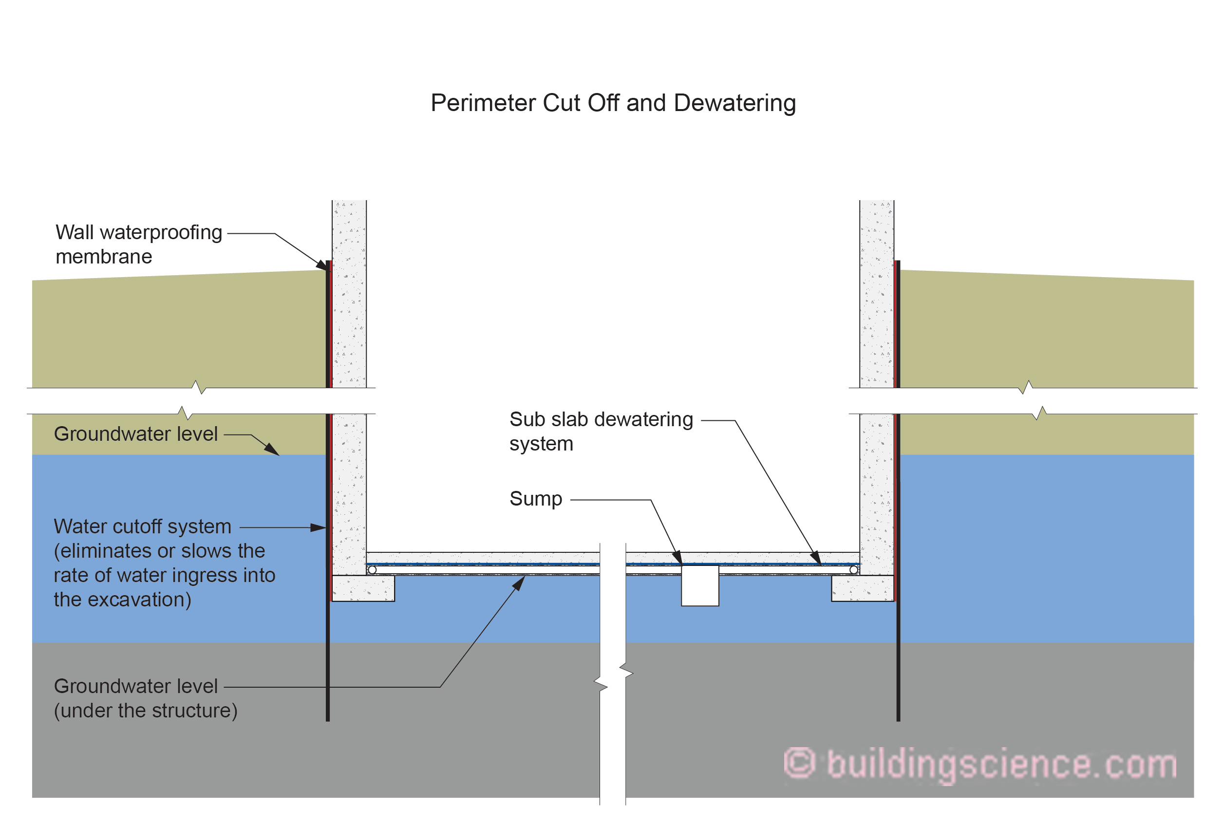
Figure 4: Below grade water management – foundation below ground water table – “perimeter cut off and dewatering” approach
Continuous Waterproofing
Figure 5 illustrates the “continuous waterproofing” approach. In this approach the wall waterproofing system is continuous with the foundation slab waterproofing system. The waterproofing system encases or “wraps” the entire foundation assembly. The groundwater is not lowered and is immediately adjacent all the foundation surfaces.
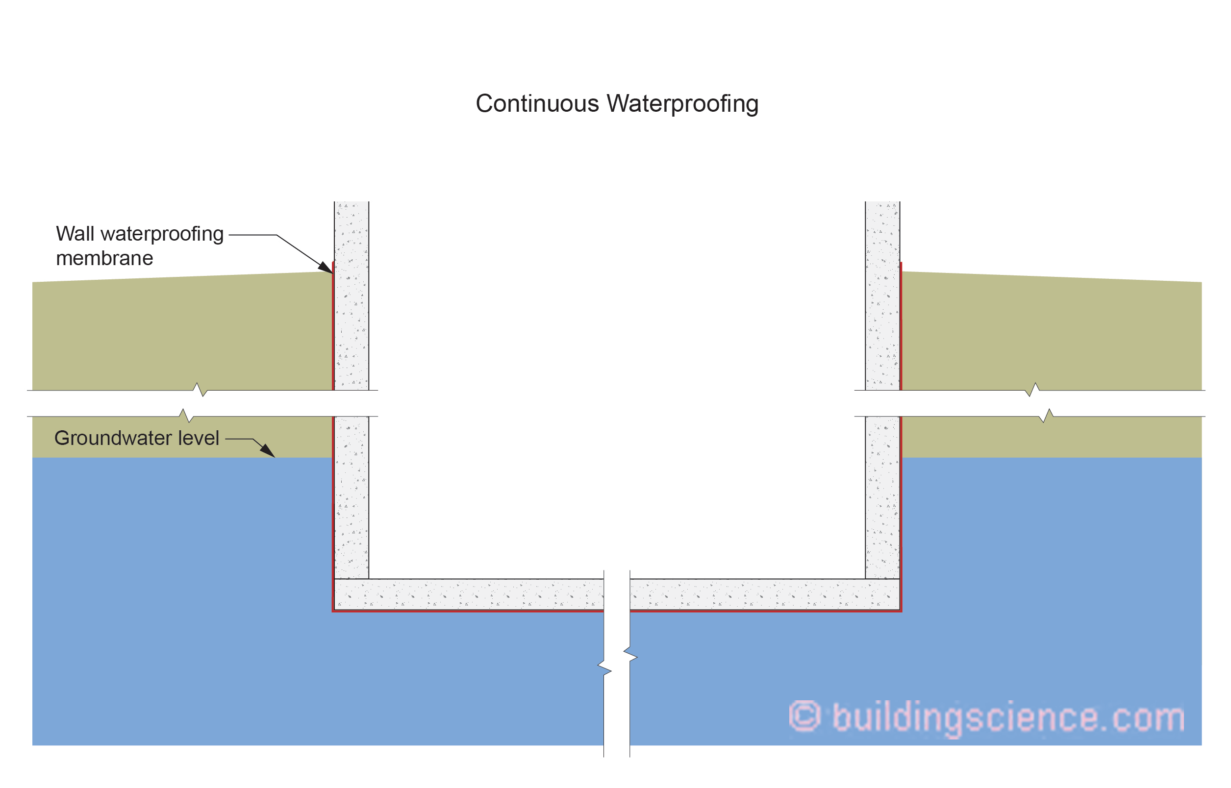
Figure 5: Below grade water management – foundation below ground water table – “continuous waterproofing” approach
Repairs
It is quite common for water leakage to occur during construction. Two standard approaches to address water leakage are typical:
• Injection sealing
• Interior drainage
Injection sealing is often successful in addressing “spot” and “intermittent” ground water leakage (Photograph 2 and Photograph 3).
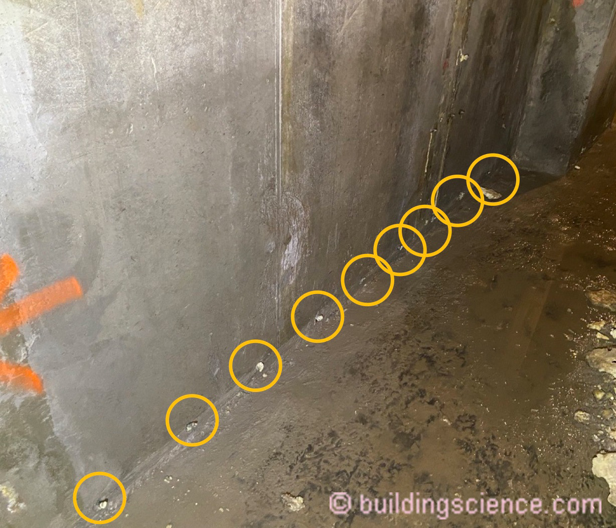
Photograph 2: Injection sealing for “spot” ground water leakage
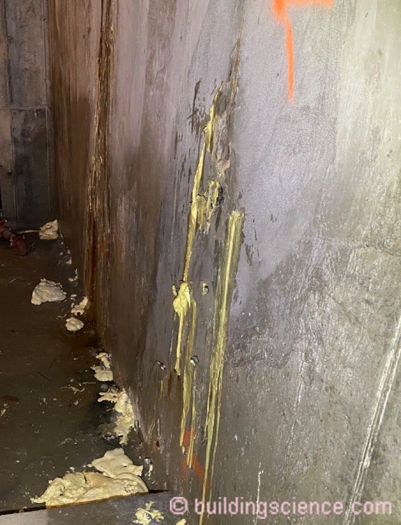
Photograph 3: Injection sealing for “intermittent” ground water leakage
Where significant ground water leakage is observed or evident the most “robust” and “conservative” approach is interior drainage which can involve lining the interior perimeter of the foundation assembly with a drainage layer (Figure 6) or the entire interior of the foundation assembly including the slab (Figure 7).
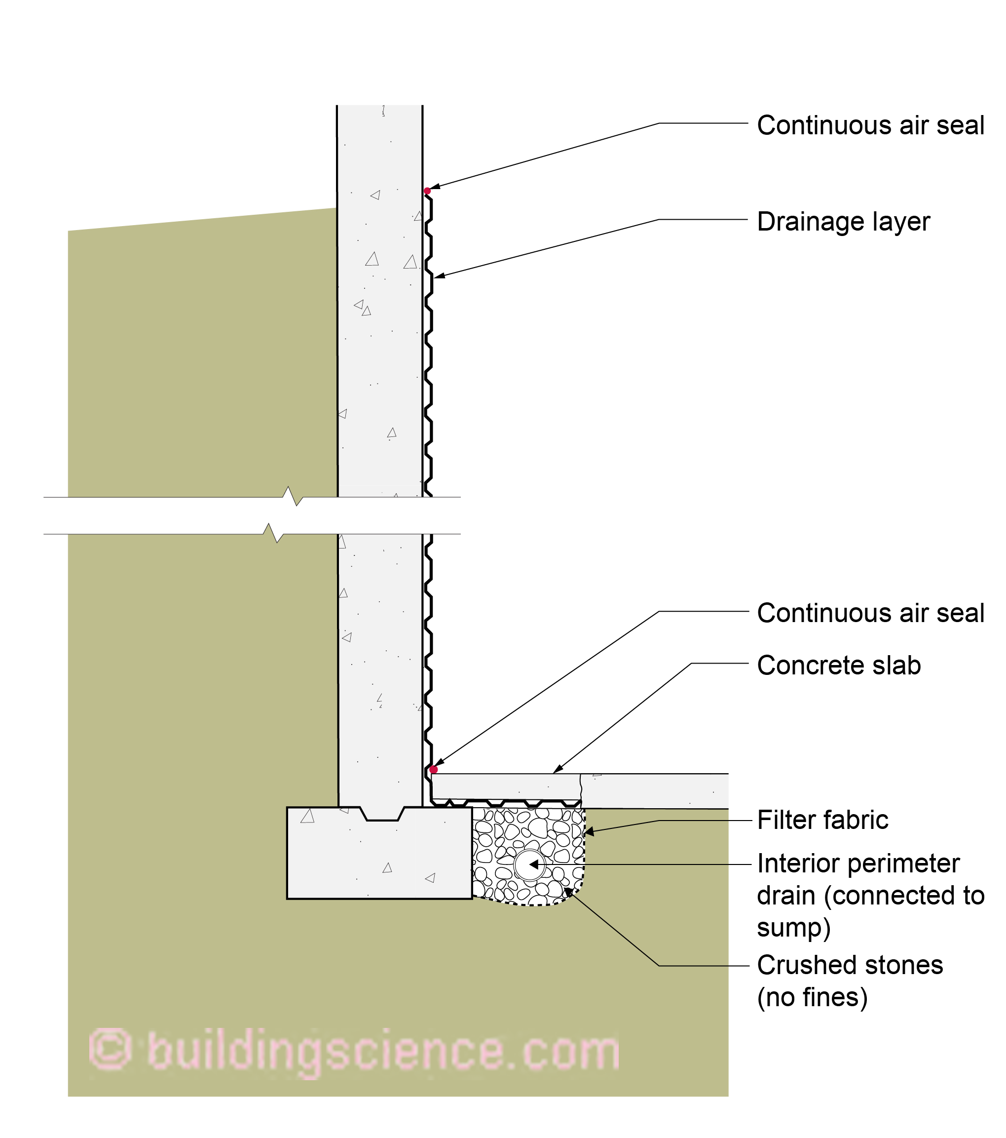
Figure 6: Drainage layer and perimeter drain on interior perimeter of foundation assembly

Figure 7: Drainage layer on the entire interior of the foundation assembly
Final Comments
Just build on top of the ground, eh! Yes, I know, I know…it is not always possible due to height limitations, density limitations. But remember, we began to dig down for frost protection in the old days…that is how we got basements. We no longer have to do that – we know how to do shallow frost protected foundations and pretty much anywhere we don’t have frost penetration we don’t dig down….except when we have no choice…see above sentence rant. Yes, we were here before (BSI-045: Double Rubble Toil and Trouble, February 2011).
Ok, so I know we will end up going down….and really going down. What is now pretty common is shown in Photograph 4 and Photograph 5. On these sites you win and lose on the service penetrations and the waterproofing details. Can we say “soldier piles”? Yes, a technology from the 1700’s that is still mainstream…the Age of Reason…Enlightenment applied to below grade water management…science and reason coming to terms with Mother Nature.
Photograph 4: Note the well-sealed service penetration in the waterproofing membrane, drainage mat and protection layer on the interior of soldier piles and wood lagging.
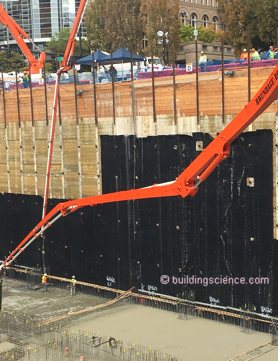
Photograph 5: Waterproofing membrane on the interior of a deep soldier pile foundation with wood lagging.