One of the most common foundation approaches to residential construction are concrete basements. They can be insulated on the inside or the outside. The basis of all basement foundations is as follows:
- Control liquid flow due to groundwater
- Control liquid flow due to capillarity
- Control soil gas
- Keep the water vapor out
- Let the water vapor out if it gets in
Groundwater control is principally accomplished by draining groundwater away from foundation wall perimeters, using free draining materials such as sand, gravel or drainage boards.
Capillary control is principally accomplished by installing capillary breaks to fill the pores in capillary susceptible materials such as concrete. The most common capillary break used in residential foundation construction is dampproofing. The dampproofing fills the pores in the concrete to control capillarity. Under concrete floor slabs, the stone layer combined with sheet polyethylene serves a similar function. Dampproofing the top of footings controls capillarity at this location. Footing dampproofing can be fluid applied or a fully adhered membrane (Photograph 1).
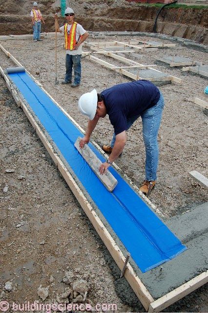
Photograph 1: Damp Proofing Footing - Damp Proofing the top of footings controls capillarity at this location. Footing damp proofing can be fluid applied or a fully adhered membrane
Soil gas control (radon, water vapor, methane, herbicides, termiticides) is principally accomplished by controlling/limiting holes and controlling the pressure difference. Locating a granular drainage pad under concrete slabs can be integrated into a sub-slab ventilation system to control soil gas migration by creating a zone of negative pressure under the slab. A vent pipe connects the sub-slab gravel layer to the exterior through the roof (Figure 1). An exhaust fan can be added later, if necessary.
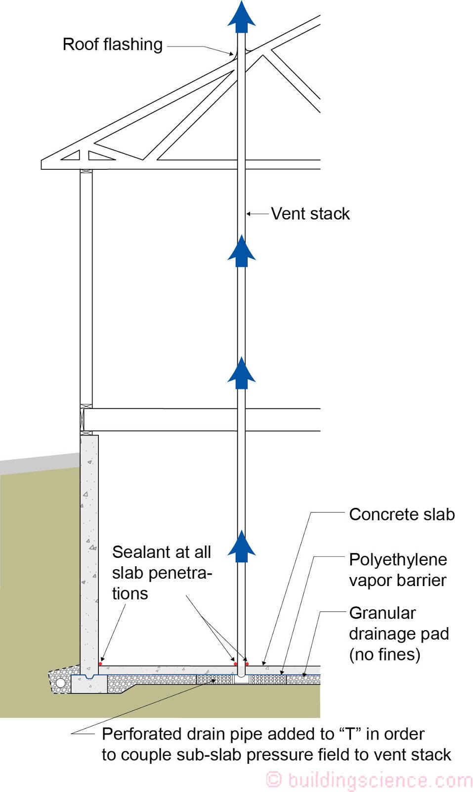
Figure 1: Soil Gas Control – Approach for basement foundations.
Controlling water vapor in foundations relies first on keeping it out, and second, on letting it out when it gets in. The issue is complicated by the use of concrete because there are thousands of pounds of water stored in freshly cast concrete to begin with. This moisture of construction has to dry to somewhere, and it usually (but not always) dries to the inside.
For example, we put coarse gravel (no fines) and a polyethylene vapor control layer under a concrete slab to keep the water vapor and water in the ground from getting into the slab from underneath. The gravel and polyethylene do nothing for the water already in the slab. This water can only dry into the building. Installing flooring, carpets or tile over this concrete before it has dried sufficiently or if a top side vapor control layer is not installed is a common mistake that leads to mold, buckled flooring and lifted tile.
Similarly, we install dampproofing on the exterior of concrete foundation walls and provide a water managed foundation system to keep water vapor and water in the ground from getting into the foundation from the exterior. Again, this does nothing for the water already in the foundation wall. When we then install interior insulation and finishes on the interior of a foundation wall in a manner that does not permit drying to the interior, mold will grow.
Foundation wall and slab assemblies must be constructed so that they resist water vapor and water from getting in them, but they also must be constructed so that it is easy for water vapor to get out when it gets in or if the assembly was built wet to begin with (as they typically are).
Drying a foundation wall assembly or floor slab after it is insulated and after surface finishes have been installed should only be done using diffusion (“letting them breathe”), not air flow (“ventilation”). Allowing interior air (that is usually full of moisture, especially in the humid summer months) to touch cold foundation surfaces will cause condensation and wetting, rather than the desired drying. It is important that interior insulation assemblies and finishes be constructed as airtight as possible but vapor permeable. This will prevent interior moisture-laden air
from accessing cold surfaces during both the winter and summer and still allow the assemblies to dry. It is extremely important not to have a vapor barrier on the interior of internally insulated basement assemblies.
The traditional approach to basement moisture control has been to locate the water control on the outside and then allow drying to the inside. Drainage, water control layers (water-proofing), capillary control layers (damp-proofing) and vapor control layers (damp-proofing) have historically been located on the outside of basement perimeter walls and crushed stone layers and plastic vapor barriers have been located under concrete slabs. The operative principle has been to keep the liquid flow due to groundwater and the liquid flow due to capillarity out of the structure and locate vapor control layers (vapor barriers) on the outside – and allow inward drying to the basement space where moisture can be removed by ventilation or dehumidification.
Two generic basement foundation approaches are typical: insulate the inside or insulate the outside. The most logical location from the physics perspective is to locate the insulation on the outside. By locating the insulation layer outward of the structure and outward of the control layers the foundation is kept at a constant temperature and the insulation system does not interfere with the inward drying of the assembly. Exterior basement insulation is completely compatible with the traditional approach for foundation water control.
Unfortunately, exterior basement foundation insulation can have significant application problems that often make it impractical to employ. The first is the difficulty in protecting the insulation layer during the construction process and subsequently during its useful service life. The second is insect control. Exterior insulation can be an “insect interstate” that provides a direct pathway into the structure.
These factors have resulted in primarily locating insulation layers on the interior. However, locating insulation layers on the interior often conflicts with the traditional approach of foundation water control – namely inward drying. Constructing frame walls, insulating the resulting cavity and covering with an interior plastic vapor barrier is common and often leads to odor, mold, decay and corrosion problems.
The most common examples of configurations of control layers and control approaches follow for residential basement foundations.
Concrete Basement Foundation With Interior Rigid Insulation
Applicability – all hygro-thermal regions
Figure 2 illustrates a concrete basement foundation with interior rigid insulation. The key to this assembly is the use of non-water sensitive rigid insulation on the interior that still permits drying to the interior. The recommended permeance of the interior rigid insulation layer is approximately 1 perm. This typically limits the thermal resistance of the interior rigid insulation layer. No interior vapor control layer is located within the frame wall thereby permitting inward drying. All interior concrete surfaces are wrapped with the rigid insulation layer – particularly at the top of the wall and at foundation “step downs”. Exterior rigid insulation is located at the rim joist floor framing to control summer condensation. When insulating sheathing is not used, rigid insulation should we installed to the interior of the rim joist or an air impermeable insulation be applied at the rim joist assembly. Note the capillary break at the top of the footing. Also note the continuous rigid insulation under the basement floor slab (Photograph 2). Further note the air sealing of the rigid insulation at the top perimeter edge of the concrete floor slab – a sealant is used to seal the top of the concrete slab to the rigid insulation and an additional sealant is used to seal the rigid insulation to the interior of the concrete perimeter foundation wall. These two seals are necessary to control soil gas ingress.
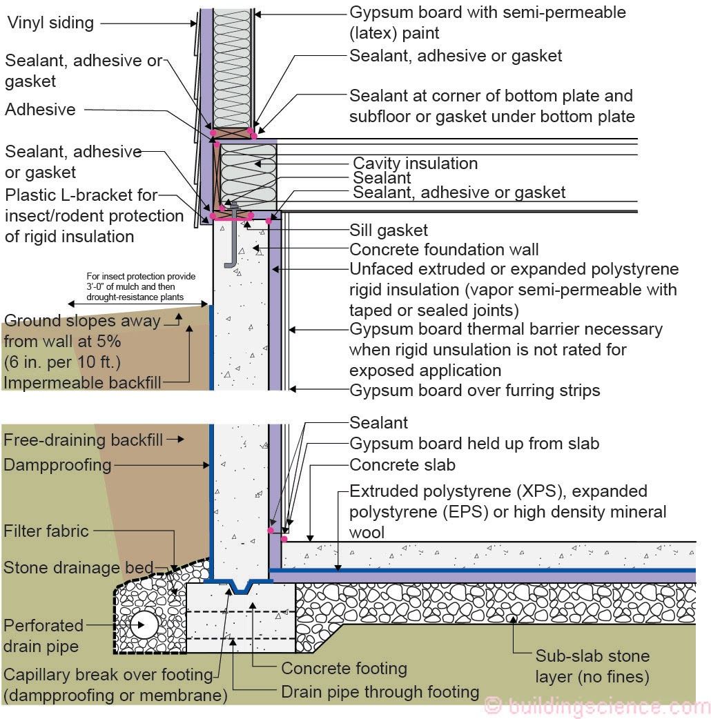
Figure 2: Concrete Basement Foundation With Interior Rigid Insulation

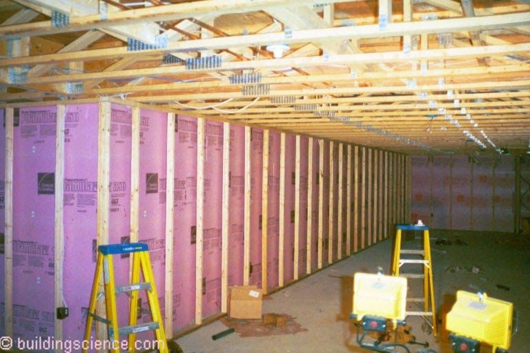
Photograph 2: Floor Slab Insulation - Continuous rigid insulation is located under the basement floor slab. This insulation can be any rigid insulation product. All work if installed over a granular layer.
Concrete Basement Foundation With Interior Spray Polyurethane Foam Insulation
Applicability – all hygro-thermal regions
Figure 3 illustrates a concrete basement foundation with interior spray polyurethane foam insulation. Polyurethane spray foam insulation can be directly applied to the interior of concrete foundation walls. High density closed cell spray foam should be used. The recommended permeance of the interior spray foam insulation layer is approximately 1 perm. This typically limits the thermal resistance of the interior spray foam insulation layer. An insulated frame wall assembly can be located to the interior of the interior spray foam insulation to increase the assembly thermal resistance. No interior vapor control layer should be located within the frame wall thereby permitting inward drying. All interior concrete surfaces are wrapped with the spray foam insulation layer – particularly at the top of the wall and at foundation “step downs”. Note the spray foam insulation applied at the rim joist assembly. Note the capillary break at the top of the footing. Further note the air sealing of the spray foam insulation connecting the concrete floor slab to the perimeter concrete foundation wall.
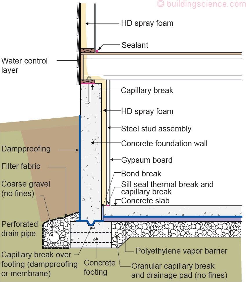
Figure 3: Concrete Basement Foundation With Interior Spray Polyurethane Foam Insulation
Concrete Basement Foundation With Interior Rigid Insulation and an Interior Insulated Frame Wall
Applicability – all hygro-thermal regions
Figure 4 illustrates a concrete basement foundation wall with interior rigid insulation and an interior insulated frame wall. The key to this assembly is the use of non-water sensitive rigid insulation on the interior that still permits drying to the interior. The recommended permeance of the interior rigid insulation layer is approximately 1 perm. This typically limits the thermal resistance of the interior rigid insulation layer and an insulated frame wall assembly can be located to the interior of the interior rigid insulation (Photograph 3). No interior vapor control layer is located within the frame wall thereby permitting inward drying. All interior concrete surfaces are wrapped with the rigid insulation layer – particularly at the top of the wall and at foundation “step downs”. Exterior rigid insulation is located at the rim joist floor framing to control summer condensation. When insulating sheathing is not used, rigid insulation should be installed to the interior of the rim joist or an air impermeable insulation be applied at the rim joist assembly. Note the capillary break at the top of the footing. Further note the air sealing of the rigid insulation at the top of the concrete floor slab – a sealant is used to seal the top of the concrete slab to the rigid insulation and an additional sealant is used to seal the rigid insulation to the interior of the concrete perimeter foundation wall. These two seals are necessary to control soil gas ingress.
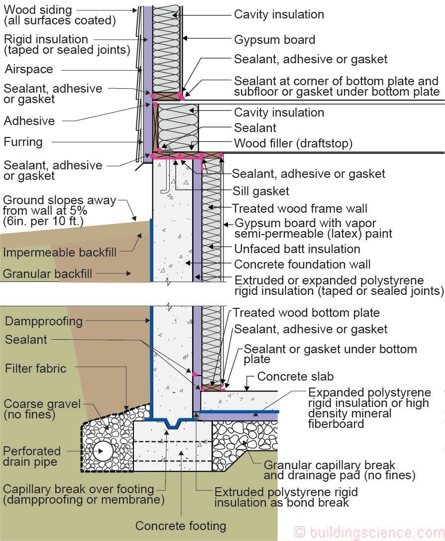
Figure 4: Concrete Basement Foundation Wall With Interior Rigid Insulation and an Interior Insulated Frame Wall
Photograph 3: Frame Wall – An insulated frame wall assembly can be located to the interior of the interior rigid insulation.
Concrete Basement Foundation With Exterior Rigid Insulation
Applicability – all hygro-thermal regions
Figure 5 and Photograph 4 illustrate a concrete basement foundation wall with exterior rigid insulation. The exterior insulation layer is protected with a sealed cement board protecting the insulation layer during the construction process and subsequently during its useful service life. Note the protective membrane strip sealed to the top of the foundation wall for insect control. Exterior rigid insulation is located at the rim joist floor framing to control summer condensation. When insulating sheathing is not used, rigid insulation should be installed to the interior of the rim joist or an air impermeable insulation be applied at the rim joist assembly. Note the capillary break at the top of the footing. Further note the air sealing of the top of the concrete slab to the interior of the concrete perimeter wall. This seal is necessary to control soil gas ingress. The exterior rigid insulation can be rigid fiberglass or rigid mineral wool – both of which provide exterior drainage and control of hydrostatic pressure (Photograph 5).
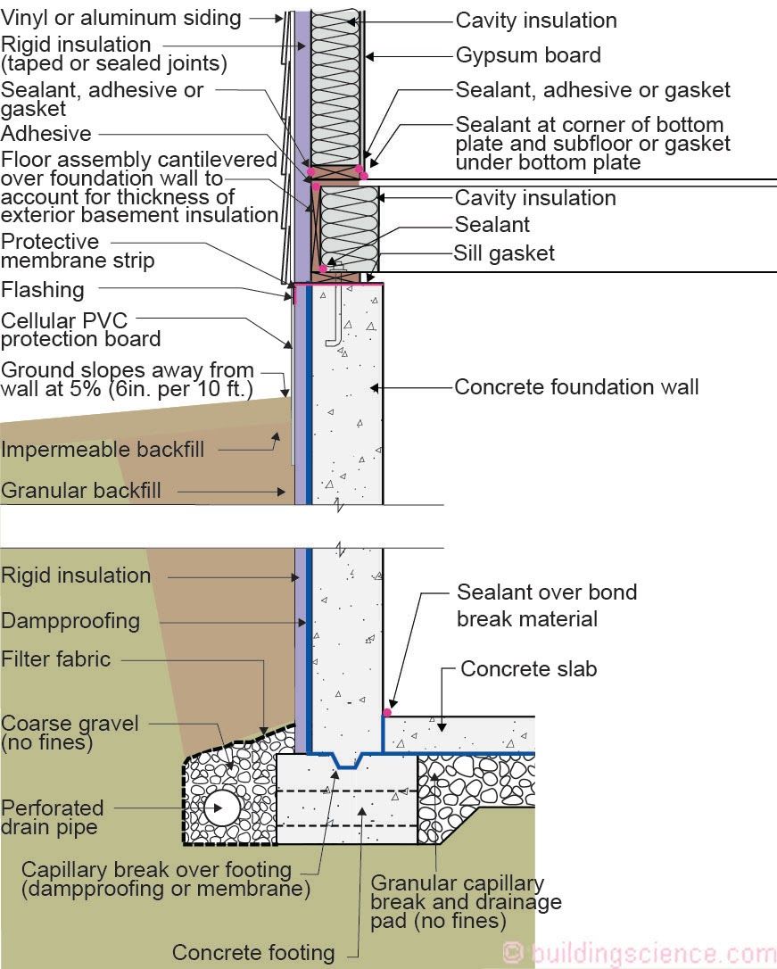
Figure 5: Concrete Basement Foundation Wall With Exterior Rigid Insulation.
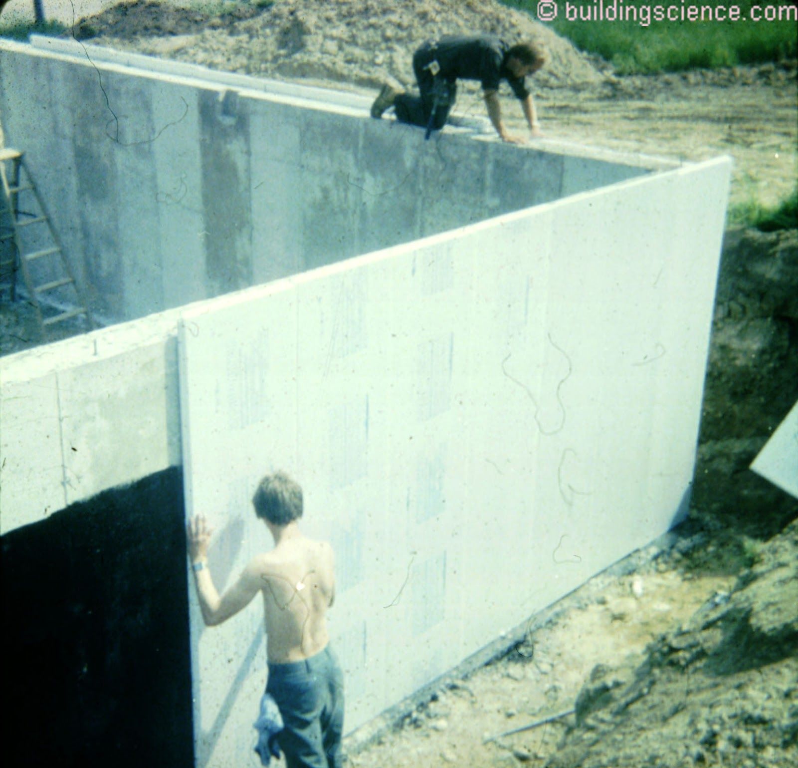
Photograph 4: Exterior Rigid Insulation – Extruded polystyrene is installed on the exterior of the concrete foundation wall.
Photograph 5: Exterior Rigid Insulation – High density fiberglass rigid insulation which provides exterior drainage and control of hydrostatic pressure.