As materials and equipment have improved, energy reduction as a goal has increasingly been replaced with the goal of net-zero energy use. But the general approach to building energy efficient homes that has been recommended has always been the same. This approach to achieving net-zero energy homes is reflected in the ten general principles for the design of net-zero energy capable houses that are presented and discussed in the first part of this paper. In the second part of the paper, specific strategies and details are described that were used for the design of the Net Zero Energy Residential Test Facility (NZERTF), a NIST laboratory in the form of a typical residence for a family of four that has been constructed on the NIST campus in Gaithersburg, MD.
1 Introduction
1.1 Background and Purpose
In 2009, the National Institute of Standards and Technology (NIST) received American Recovery and Reinvestment Act funding for the construction of a net zero energy residential test facility (NZERTF) on the NIST Campus in Gaithersburg MD. The facility was to be constructed as a typical residence for a family of four that could be demonstrated to achieve net-zero site energy use on an annual basis. Net-zero energy use was to be accomplished through the combination of low energy loads due to a high performance enclosure, efficient mechanical systems, and low energy fixtures and appliances in combination with site-generated energy using roof-mounted solar panels. Following the demonstration of net-zero site energy use, the facility is to be used by NIST’s Energy and Environment Division as a research laboratory to test and measure residential energy technologies, indoor environmental quality, materials, and other aspects of sustainable performance in a realistic context.
Building Science Corporation (BSC), a building science consulting and architecture firm, has been researching and designing durable, healthy, and energy efficient homes for 20 years and is one of the original teams in the U.S. Department of Energy’s Building America program1. During this time, BSC has developed proven methods for construction of high performance enclosures and a practical approach to design for low energy homes. Using this experience and expertise, BSC worked with NIST to develop the architectural and mechanical design of the NZERTF. BSC’s work was partially funded by the Building America program.
The purpose of this report is to describe a general approach to the design of new, low energy, net-zero capable homes and then to describe the specific strategies used in the architectural and Mechanical/Electrical/Plumbing (MEP) design of the NZERTF that promote low energy use, good indoor air quality, durability, minimal environmental impact, and net-zero energy capability.
1.2 Approach
Trends in the United States and throughout the world have motivated builders to build low energy use, environmentally friendly and affordable, or at least more economical, homes. As materials and equipment have improved, energy reduction as a goal has increasingly been replaced with the goal of net-zero energy use. But the general approach that is recommended has always been the same. This is reflected in the general principles that are enumerated in the first part of this report – namely that reduction of energy use through means that are consistent with the homeowner’s way of life and available technologies is the primary goal; on-site generation of energy is simply an alternative, clean and renewable source for the energy after energy consumption has been reduced as much as is feasible.
The second part of the report explains the strategies and details that were included in the design of the NZERTF specifically to promote energy efficiency and durability of the various components and systems. The uniqueness of the NZERTF project, including government procurement and a construction process that restricts communication between the contractor and the architect, and the fact that construction of low energy use homes requires non-standard residential techniques and processes meant that more design detail and explanation was needed than is typical for residential construction. As such, an important component of the NZERTF design was to promote design communication by including sufficient design detail information in the construction set to indicate the adjustments to standard practice that are needed in the construction of low energy use homes.2
2 General Design Approach for a Net-Zero Energy House
2.1 What is a net-zero energy house?
A zero energy house is one in which all energy needs of the house are met using energy that is generated on-site using renewable sources. A zero energy house is independent of all off-site energy sources and must have the capability to harvest and store energy on the site. Most homeowners do not have the resources to meet these criteria, i.e., access to on-site clean and renewable energy sources, sufficient energy storage capacity, and low enough energy use on a continuing basis. On the other hand, a net-zero energy house is one in which the total amount of energy consumed in a year is less than or equal to the total amount of energy generated on-site during that year. While this still requires on-site energy generation, a net-zero energy house is connected to the electrical grid and the grid acts as the “storage” for the site-generated energy that is not immediately consumed.
While meeting the goal of net-zero energy is less difficult than the more stringent zero energy goal, it still requires a significant energy reduction effort. Reduction of energy consumption by houses has been a topic of research for decades but has received more attention recently as the environmental impact of continued and growing use of fossil fuels becomes evident. New building materials and building techniques as well as availability of more efficient equipment and appliances have made construction of low energy houses possible though progress has been
somewhat offset by increasing house sizes and the extensive use of electronic devices in homes.3 Nevertheless, many low energy houses are being built and there are a number of case studies that demonstrate that net-zero energy use is being achieved.4
For a low energy house, a significant portion of the total annual energy consumption can be attributed to miscellaneous electric loads (MELs), also called plug loads. The energy consumption of MELs is primarily a function of the activities of the occupants of the house rather than the low energy characteristics of the house. For this reason, it is more accurate to refer to the design of a new house as being net-zero energy capable rather than being net-zero energy.
The term “net-zero energy” as used in this paper could refer to either net-zero site energy or to net-zero source energy.5 Energy use reduction is the goal in either case, but the calculation used to determine energy consumption for site energy is based only on energy use at the site whereas source energy use takes into account the energy used to generate and to deliver energy to the site as well as what is used at the site. Source energy consumption more accurately reflects the environmental impact of energy use.6
2.2 Ten Principles for Design of a Net-Zero Energy Capable House
The overall approach for designing a net-zero energy capable house is to first incorporate as many energy reducing techniques as are economically and technically feasible and appropriate for the project. The next step is to do a thorough energy use analysis to project total annual energy consumption, revisiting earlier decisions and making adjustments as needed to get the projected consumption as low as possible. Finally, enough on-site renewable energy is provided to exceed the projected annual energy consumption. These steps would conventionally be done using weather conditions in a typical year, appreciating that deviations from that typical year could make the goal of achieving net-zero operation either more or less difficult.
It should be noted that this approach does not start by calculating the maximum potential for renewable energy generated in a year and then designing with the goal of keeping annual energy consumption below that amount. Instead, the primary goal is to reduce energy use as much as possible. The on-site renewable energy reduces, but does not eliminate, the dependence on external energy sources since electricity from the grid is used at those times when the energy needed within the home exceeds the energy being generated. Therefore reducing energy consumption remains the most important factor.
The ten principles described in this section are consistent with the approach of minimum energy consumption and using renewables to meet the annual energy requirements. They are derived from Building Science Corporation (BSC)’s continuing research and experience with low energy houses, much of which has been done in conjunction with the U.S. Department of Energy’s Building America program.
The design and construction of a net-zero energy capable house requires a team effort. The capabilities needed within the team include owner, architect, building contractor, building scientist, structural consultant, MEP professional, energy analyst, renewables consultant, and landscape designer. With the exception of the owner, all team members should have experience with low energy house design and construction. Design and construction of a net-zero energy capable house differs from, and is less forgiving than, standard residential design and construction.
2.2.1 Principle 1: Design for comfort and function
While it may seem strange that the first principle for a net-zero energy house design does not mention energy use at all, a house that does not meet the comfort level and functions needed by the occupants will not be used or maintained in the manner intended. As a result, the energy use assumptions made during the design will be invalid. The design should strive to meet these requirements with as little energy use as possible.
For example, the placement of windows can enhance comfort level without using any energy. Operable windows can be arranged to provide airflow by natural ventilation when neither heating nor cooling is needed. During the winter, sunlight through south-facing windows can enhance comfort to occupants through radiant heat transfer. However, these windows could also cause overheating in the summer (and thus increased energy use to maintain comfort) so some means of shading of the windows, such as appropriately sized overhangs, would be needed.
Because of this first principle, tradeoffs may be needed between a design of the smallest, most compact home layout possible and a more expansive structure that better meets the living style of the occupants. With careful orientation of the building and layout of space, with a high performance building enclosure and with high efficiency HVAC systems and appliances, the energy use can be kept low even for a more expansive building form. While small and compact is a good energy reduction technique, if it doesn’t meet the needs of the occupants, additions will soon be made which will increase the floor and surface area, increase energy use and require further adjustments if net-zero energy use is still to be met.
In heating or cooling dominated climate zones, delivery of heated or cooled air to the living spaces in a consistent manner is a major factor for comfort and actual energy use. If some living space is felt to be too hot, too cold or too stuffy, adjustments will be made by the occupants (for example, leaving windows open or continually adjusting the thermostat or ventilation controls) that will undermine the efficiency of the enclosure or HVAC design.
A house can be designed and built to be net-zero energy capable, but ultimately it is the occupants’ use of the house, generally driven by their comfort and functional needs, as well as the way that the house is maintained that determines whether the net-zero energy goal is met.
2.2.2 Principle 2: Establish an airtight building enclosure
The building enclosure separates the indoors from the outdoors. Therefore it must provide for airflow control as well as water, vapor and thermal control. The design of a high performance enclosure, as is required for a net-zero energy capable house, must clearly specify how these functions are to be provided.
Uncontrolled air leakage across the enclosure can be responsible for much of the energy use for heating/cooling of a house as well as being the primary source of moisture within the structure.7
Airtightness of the enclosure is one of the most important requirements of a low energy house. Airtightness is provided by the airflow control system of the enclosure. This is a continuous system of air impermeable materials and building components (such as windows and doors) that separates the conditioned space of the house from unconditioned air and from contact with the ground. The effectiveness of the airflow control system of a house is usually measured in terms of leakage rate (Q50) or air changes per hour (with units of h-1) measured under a fan pressurization test with a 50 Pa pressure differential between the inside and outside air. Building
Science Corporation set the target airtightness for the NZERTF at 1.5 h-1.
An effective airflow control system is one that is durable and is simple to construct. For a house with a conditioned attic and a conditioned basement, the boundary between conditioned and unconditioned space is the same as the exterior of the house. In this case, wrapping an air barrier membrane completely and continuously around the exterior sheathing of the roof and walls creates a very effective airflow control system provided there is appropriate air sealing to the foundation and at the windows, doors and all wall/roof penetrations. Inclusion of the basement and attic in conditioned space has additional advantages. Location of mechanical equipment and ductwork in the conditioned space reduces wasted energy. Conditioned attic and basement space is more useful, even if just for storage. And an unconditioned basement can increase the likelihood of indoor air quality and moisture problems. If the house is airtight and well insulated, the overall reduction in wasted energy consumption will generally compensate for the increased total volume of conditioned space.
If the attic or the basement is not conditioned, or if there is an attached garage, it is more difficult to establish a sufficiently tight air control layer system since components of the airflow control layer must be connected through the discrete structural elements of the enclosure. In these cases, it may be more effective to establish the air control layer system on the interior side of the enclosure using a method called the “airtight drywall approach.”8 This method requires very careful attention to detailing, taping and caulking in order to create a continuous air control layer system around the entire conditioned interior, but it is effective when done correctly.
While airtightness alone will not achieve net-zero energy use, it is one of the more effective ways to reduce excess energy consumption. Other benefits of airtightness include improved durability of the wall materials due to better moisture control and improved comfort due to reduced drafting and better control of the source of incoming air and any contaminants it may bring into the building.
2.2.3 Principle 3: Provide controlled ventilation
All buildings require ventilation – the purposeful, controlled flow of outside air into conditioned space. ASHRAE Standard 62.2 “Ventilation and Acceptable Indoor Air Quality in Low-Rise Residential Buildings” specifies the amount of ventilation that the system should support based on the size of the house and the number of bedrooms. One method of meeting ASHRAE Standard 62.2 is through the use of an “exhaust-only” ventilation system. In this type of system, air is removed from the house using fans which exhaust air from the baths and kitchen to the outside; this creates a pressure differential forcing outside air to enter the house through any air infiltration paths that exist in the enclosure. From an energy use standpoint, this approach is not optimal since conditioned air is exhausted from the house. From an interior air quality standpoint, this approach is not optimal since the unfiltered outside air enters through unintended and potentially contaminated passageways in the building enclosure.
An airtight, high performance enclosure works best with a balanced ventilation system – one that mechanically controls and balances the flow of both the supply air and the exhaust air. By controlling the path of the supply air, the incoming air can be filtered and distributed appropriately within the house. Many balanced systems also perform heat exchange between the streams of incoming and outgoing air. The heat exchange reduces the excess energy use caused by exhausting conditioned air and bringing unconditioned air directly into the interior.
There are two types of balanced air systems with heat exchange: an HRV (heat recovery ventilator) system that exchanges heat between the supply and exhaust air streams and an ERV (energy or enthalpy recovery ventilator) system that exchanges heat and moisture between the air streams. While these systems provide some energy recovery, they also require energy to operate the fans, so it is important to specify a properly sized system with a highly efficient and quiet fan.
There are a variety of ways to configure a balanced ventilation system. Three options typically considered for a low energy house include integration with the central air system, integration with the bath exhaust system, or independent installation with a dedicated duct system.9 Design, installation, and commissioning of these systems must be done by an HVAC professional who is familiar with the systems and with low energy houses.
BSC typically commissions the ventilation system to provide about half of the ASHRAE 62.2- specified rate for normal use. BSC also believes that the controls should include a higher setting that allows the installed system to be run at the ASHRAE 62.2-specified rate. If the ventilation system is part of the bathroom exhaust system, a timed boost switch is needed in the bathroom. But perhaps the most important requirement is that the controls be simple and easy to understand and that the occupants fully understand the intended use of the system and how changes to that will impact air quality and energy use.
For a very tight house, the operation of the kitchen range hood, the clothes dryer or other exhaust devices that are not integrated with the ventilation system can cause some depressurization of the house. In this case, makeup supply air will need to be provided when any of these devices are operating.
It is recommended that a passive radon mitigation system be installed in all tight houses that have basements or slab-on-grade floors. This is a sub-slab ventilation system with a vent stack extending up through the roof creating a negative pressure zone under the slab so that soil gas is vented out. If needed, a fan can be added to the system in the future.10
2.2.4 Principle 4: Install insulation that exceeds current energy code requirements
While airtightness reduces direct loss of conditioned air by infiltration through the enclosure, insulation resists transfer of heat by conduction through the enclosure. The thermal control system of the enclosure consists of all those materials that are installed to control the transfer of heat through the enclosure. Resistance to heat flow is usually quantified in terms of R-value. When comparing two materials, if the same amount of the two materials is used, heat transfer through the material with the larger R-value will be less than that through the material with the smaller R-value.
For houses using standard residential construction techniques, exterior wall insulation is applied in the bays between the framing members. Since walls are composed of a combination of materials, some of which are highly conductive, the overall R-value of the wall is considerably less than that of the insulation. For example, a 38 mm x 140 mm (2x6) wall framed at 406 mm (16 in.) on center (o.c.) with an R-value of 3.3 m2∙K/W (19 ft2∙h∙°F/Btu) insulation installed in the framing bays has an overall wall insulation R-value of 2.4 m2∙K/W (13.7 ft2∙h∙°F/Btu).11 This takes into account not only the R-values of all materials in the wall but also the effect of thermal bridging that the framing introduces through the walls.
Use of continuous insulation in addition to the framing bay insulation is recommended for high performance enclosures to reduce thermal bridging, especially in a heating dominated climate. This can be accomplished by applying a continuous layer of insulation to the exterior side of the walls or to the interior side of the walls, or by construction of a double wall so that the framing does not extend completely through the wall. Similarly, minimizing thermal bridging through the roof (or attic floor) framing can be accomplished by applying a continuous layer of insulation to either the exterior or interior side of the assembly. If it is applied to the interior, special construction techniques may be needed to provide sufficient depth along the eave for the insulation.
The 2012 International Energy Conservation Code (IECC) (International Code Council, 2012) for residences specifies minimum performance requirements for the enclosure based on the climate region in which the house is located. In general, the minimum R-values specified by the IECC code are not consistent with a high performance enclosure. Instead, high performance enclosures should use as much insulation as is possible (exceeding the IECC requirements), include continuous insulation to reduce thermal bridging, and install the insulation so that there are no internal air gaps (and so that the insulation will not shift or pull away to create air gaps over time). The latter requirement is to prevent convective looping within the insulation that can undermine its thermal resistance function.
Windows are the weakest component in the thermal control layer of the building enclosure because of the low R-value of glazing. However, windows are important for the comfort and function of the house (e.g., natural lighting and views). Where possible, the size and number of windows in locations that contribute the most to heating and cooling loads should be minimized. The most important characteristics of the windows are an R-value of at least 0.88 m2∙K/W (5 ft2∙h∙°F/Btu) (higher in heating dominated climates), air and water tightness, and installation in a way that supports continuity of the airflow, water, and thermal control systems of the enclosure.
Similar to the airflow control system, the thermal control system is located along the boundary between the conditioned and unconditioned air. As with the airflow control system, connections between components of the system must be detailed carefully so that the control function is provided continuously. While a discontinuity in the airflow control system results in direct loss of conditioned air through air infiltration, a discontinuity in the thermal control system results in reduced overall resistance to heat transfer because of thermal bridging. In either case, the discontinuity causes excess energy use to maintain the interior conditioning and may contribute to potential envelope moisture problems.
2.2.5 Principle 5: Establish water and moisture control for the building enclosure
There are many aspects of water and moisture control required for any building (see Figure 1). The site must be graded to drain surface water away from the foundation wall of the building; groundwater must be kept away from the foundation and footings; the exterior of the building must be designed to drain water off of, and away from, the building; the building enclosure must have a water control system which reduces the likelihood of water from penetrating any further into the enclosure and redirects it to the outside, usually via flashing; and, any water or moisture that does manage to get into the enclosure must be able to dry. Failure to provide for these conditions will ultimately damage the building structure and materials and contribute to poor indoor air quality.

Figure 1: Fundamental Rainwater Control
While these requirements apply to all buildings, the design and implementation of the water control system of the enclosure and the ability for moisture in the enclosure to dry need more attention for a high performance enclosure. Due to the airtightness, type of materials, and thickness of a high performance enclosure, it cannot be assumed that water or moisture that gets into the enclosure will be able to dry. The design of the enclosure must minimize the potential for water getting past the water control system but also provide specific support for drying of any water or moisture that does get in.
The water control system for the roof and walls of a house is usually provided by a water control layer (e.g., building wrap or membrane) located just behind the cladding or roofing that is interconnected with flashings, window and door installations, and other penetration drainage mechanisms. All connections between components of the water control system must be shingle- lapped so that water does not get behind the water control layer as it flows down. If tape is used on the water control layer, it must be tightly adhered to the surface; any “fish-mouthing” at the top edge of the tape will collect rather than shed water, ultimately allowing water through the water control layer. With the water control layer directly behind the wall cladding, there needs to be a gap between the cladding and the water control layer sufficient to allow drainage.
Provision for drying of the wall depends on the design of the high performance enclosure. For example, if drying to the exterior is prevented by the presence of vapor impermeable materials on the exterior, such as insulating sheathing applied over the structural sheathing, there must be sufficient vapor permeability of the materials to the interior side of the sheathing to allow drying. Since this vapor permeability will also allow vapor from the interior to enter the enclosure, an analysis must be made to verify that the amount of exterior insulation is sufficient to keep the structural sheathing warm enough to minimize the risk of condensation.12
2.2.6 Principle 6: Configure building on site to maximize renewable energy potential
To achieve a net-zero energy house, clean and renewable energy must be generated on site. This is usually in the form of solar energy systems, but it could also be a ground source heat exchange loop, wind or water power, or some type of biomass. The site layout and the orientation and form of the house should take into account plans for the inclusion and possible future addition of renewables.
For solar energy, the location on the site with the largest unshaded southern exposure needs to be reserved for the solar renewables. For photovoltaics, this location may be used for a ground- mounted array of panels or for a roof-mounted array on a south facing sloped roof of the house or of an outbuilding such as a garage; for solar thermal, the panels should be placed as close to the point of use as possible to minimize heat loss and frictional losses in the pipes between the panels and the end use. When using a south facing roof for solar panels, it is best if the slope of the roof is within the optimal range recommended for solar panels in the region, which is typically the same as the latitude of the site13; in this case the panels can be laid flat on the roof which will maximize the number of panels that can be installed as well as their efficiency. If the site is large, a site survey and shade analysis may be useful in determining the optimal location for the solar array. For a small site, the best solution is to simply incorporate as much unshaded south facing roof surface as possible; Figure 2 shows one such installation in which the entirety of the available roof is used for solar panels.
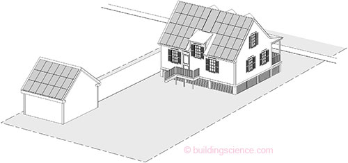
Figure 2: Solar Panel Distribution on a Small North-Facing Lot
Passive solar energy can be collected and transferred into the house by placing windows on the southern exposure of the house. However, too much exposed southern glazing can cause overheating in the summer and even in the winter. Therefore, careful sizing and placement of the windows and design of overhangs or other shading methods are needed in order for this solar energy strategy to actually reduce net energy use.
For wind power or a ground source heat exchange loop, the location of the renewable equipment depends on other site features such as soil type or predominant wind direction. Thus a general layout of the renewables equipment on the site will inform the options for the placement and orientation of the house.
In addition to orienting or placing the new house in a location that is compatible with provision of the renewable energy source, orientation for other energy reduction strategies appropriate for the climate region should be considered. For example, the orientation, layout and form of the house should be arranged to take advantage of daylighting, to support passive solar heating, to avoid unwanted solar heat gain, and to create unconditioned or semi-conditioned living space such as a three-season porch.
2.2.7 Principle 7: Select efficient mechanical equipment
For standard residential construction, heating and cooling typically consumes more than half of the annual energy use in most climates. With a high performance enclosure, the heating and cooling load is significantly reduced and accounts for a smaller part of the total energy consumption. For example, for a BSC case study of a net-zero energy capable house design in a heating dominated climate, the source energy consumption for heating and cooling accounted for more than 54 % of the total annual source energy use if standard construction were to be used. (Building Science Corporation, 2010a) However, with a high performance enclosure, the heating and cooling source energy use was reduced to 25 % of the total (see Figure 3).
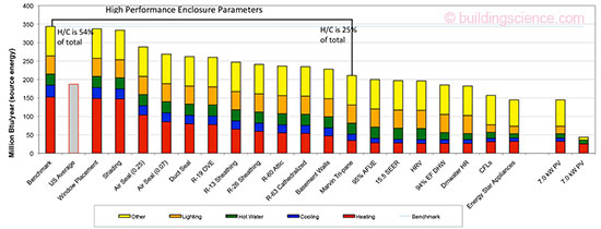
Figure 3: Parametric Study for Concord Cape Prototype; taken from Building Science Corporation (2010a)14
With the smaller heating and cooling loads of a high performance enclosure, smaller and more efficient mechanical equipment can be selected to further reduce energy use. Options for highly efficient forced air heating and cooling include an efficient furnace for heat and an efficient heat pump for cooling; an efficient heat pump for central air heating and cooling; or one or more mini-split air source heat pumps for both heating and cooling. A hydro-air system with a sealed combustion high efficiency gas boiler may also be an efficient heating solution. It is important that the heating and cooling system not be oversized since, in most cases, that will reduce the overall efficiency of the system. For a small house with very low heating and cooling loads, use of a mini-split system may be the only system that is small enough. The most important characteristics are that the system be efficient, be sized correctly, and be installed, operated, and maintained in a way that is consistent with the capabilities of the system.
Even though electricity is generated on site for a net-zero energy capable house, an all-electric system may not provide the most energy efficient solution. If natural gas is available at the site, the use of an efficient sealed combustion gas rather than electric furnace or boiler may result in lower source energy consumption.
Traditionally, dehumidification of living space has been assumed to be adequately provided by the air cooling system. However, with the reduced cooling load of a high performance enclosure, the cooling system may not run long enough to provide adequate dehumidification. Therefore, supplemental dehumidification should be considered in climates that require cooling.15
All ductwork and mechanical equipment should be located in conditioned space; otherwise it is any leakage or heat transfer leads to wasted energy. In addition, supply trunks should be insulated and all ductwork should be sealed so that conditioned air is delivered as designed. Hot water heat loss is reduced by insulating the pipes and by placing all hot water use in the same general section of the house. Energy efficient options for hot water heating include a gas water heater, a solar hot water system with gas or heat pump backup, or gas or electric tankless systems. Any gas space and water heating appliance used must have sealed combustion.
All of the energy efficient mechanical systems should be designed, installed, and commissioned by an HVAC professional who is familiar with the specified systems and with low energy houses. Controls for the equipment need to be straightforward and fully explained to the occupants.
2.2.8 Principle 8: Select efficient lighting layout, fixtures and appliances
The best way to keep energy consumption of interior lighting low is to design a lighting system that meets, but does not exceed, the needs of the occupants. The design should clearly distinguish between ambient lighting, task lighting, and accent lighting based on the functions to be performed at particular locations within the house. The ambient lighting level can be quite low. The building orientation, room layout and window placement should maximize useful daylighting in those areas that are used during the day. High efficiency, Energy Star qualified lighting fixtures with fluorescent or LED lamps that provide high quality light should be specified. And finally, lighting controls should be convenient and simple.
The refrigerator, dishwasher, and clothes washer should be Energy Star certified. All appliance selection should also take into account the posted energy use ratings to determine how the different products available will contribute to energy consumption. Less energy will be used if the appliances selected adequately meet the occupants’ requirements but do not exceed what is needed in size or in function. If natural gas is available at the site, selection of gas appliances may result in lower source energy use.
In general, integrated home control and monitoring systems are not needed for a low energy house. Inclusion of any such system should be based on the expectations of the occupants rather than installed as an energy reduction strategy.
2.2.9 Principle 9: Use energy modeling to further reduce and project total energy use and to size on-site renewables
While energy modeling or other forms of energy use projection will have been used to make decisions throughout the design, the primary focus up to this point has been selecting reasonable low energy use strategies and meeting the requirements of the occupants. The next step is to perform a thorough and detailed analysis of the projected energy loads and energy consumption.
The energy modeling method needs to be detailed enough to accurately reflect the important characteristics of the location, the site, the enclosure and the layout of the house, to calculate and categorize loads (heating, cooling, hot water, etc.), to size mechanical equipment, and to project and categorize energy consumption on daily, monthly, and yearly bases. Methods to effectively model newer energy saving technologies such as tankless water heaters, solar thermal with a backup water heater and geothermal systems are also needed. Using the information generated by the analysis, additional energy reduction can be explored or tradeoffs between other possible strategies can be considered.
After the energy use has been reduced as far as is possible within the constraints of the project, the size and layout of the on-site renewable energy can be finalized. If there is sufficient potential for the on-site renewable energy to exceed the final projected annual energy consumption, the designed house will be net-zero energy capable. Whether the house meets the goal of net-zero energy or not will depend upon the future actions of the occupants.
2.2.10 Principle 10: Include coordination and commissioning of systems in the project plans
The construction techniques required for a high performance enclosure have some important differences from those used for standard residential construction. Similarly, the mechanical equipment specified for a low energy house differs from standard equipment. If the building enclosure is not built correctly or the mechanical equipment is not installed and commissioned correctly, not only will the house fail to be low energy but it will also be very uncomfortable. Therefore, the project plans and documents must be very specific about construction techniques, testing and verification to be performed and commissioning required of all systems including the renewables.
The best results will be obtained if everyone on the team understands the goals of the project, the reasons that particular techniques and tests were specified, and the operational parameters that need to be met by the specified equipment.
3. Design of the NZERTF
All of the principles described in Section 2 were applied to develop the strategies for reaching the net-zero energy goal during the design of the NZERTF. The following sections describe how the resulting design incorporates and supports specific energy reducing techniques to be net-zero energy capable.
3.1 Overview of Design of NZERTF
This section covers the background, general requirements and design decisions made about the form and layout of the house.
3.1.1 Purpose and General Requirements
In the fall of 2009, the Energy and Environment Division of NIST’s Engineering Laboratory began to work with BSC to design a high performance, net-zero energy capable house to be located on NIST’s Gaithersburg, MD campus for use as a research and test facility. The style and size of the house was to be a typical residence that might be built in the local suburban area for a family of four. The house is to be used as a demonstration home for the first year following completion to show that net-zero energy use can be met using roof-mounted photovoltaics while still maintaining the aesthetics and life style typical for homes in the surrounding area and delivering indoor environmental quality that meets or exceeds that in typical homes. During the demonstration phase, energy use is to be tracked for a simulated family of four “occupying” the house using techniques developed by the NIST researchers. Following the demonstration phase, the house is to be used by the NIST researchers as a measurement science laboratory to develop and assess performance metrics and evaluate current and emerging systems for net-zero energy homes.
3.1.2 The NZERTF Site
Gaithersburg, MD is in climate zone 4A (Mixed Humid). The general criteria for this climate zone are as follows: more than 508 mm (20 inches) annual precipitation, less than or equal to 4500 cooling degree days at 10 °C (50 °F) basis and less than or equal to 5400 heating degree days at 18 °C (65 °F) basis. While the heating load often predominates in a Mixed-Humid climate, the cooling and humidity loads are also significant.
The site for the house is a large south-facing lot that rises about 3 m (10 ft) above the road within the first 30.5 m (100 ft). The slope is less steep in the other directions. There are mature trees along the east and west edges of the site. Since solar energy is to be used to meet the net-zero energy goal, shading studies of the site were performed by NIST. It was determined that the best location for capturing solar energy would be just north and west of the crest of the hill. Use of this location required that several plum trees to the south and southwest be relocated to other parts of the campus, but all of the mature trees aligning the site to the east and west could remain. While these trees provide some obstruction of view from the east and west, the site – and therefore the house – is clearly visible from both the south and the north (see Figure 4).
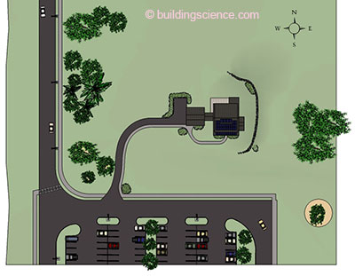
Figure 4: NZERTF Site Plan
Electricity, communication cable, natural gas, water, sewer, and storm drainage are available at the site. During the demonstration phase, the house is to be configured as an all-electric house. Following that, natural gas equipment will be used, so gas lines were brought to the house and capped for future use. In addition to the solar energy, geothermal energy is planned for use after the demonstration phase so three types of geothermal loops were installed to the south, to the northwest and to the north of the house and capped for future use.
3.1.3 House Design Decisions for Net Zero Goals
The design of the house is based on a modern, enlarged Dutch Colonial style with a full unfinished basement, a first floor with a side extension to the east for additional living space, and a nearly full second floor with front and rear shed dormers (see Figure 5). Porches on the front and back of the house provide additional living space during the shoulder seasons and add exterior features to the two most visible sides of the house. The interior of the house includes a typical modern kitchen at the rear with adjacent dining area, a living room at the front, a master bedroom suite on the second floor, three additional bedrooms one of which is on the first floor and can be used as an office, and three full bathrooms. The total interior living space is about 250 m2 (2700 ft2). This style of house with a similar interior layout can be found throughout the mid-Atlantic region as well as in New England.
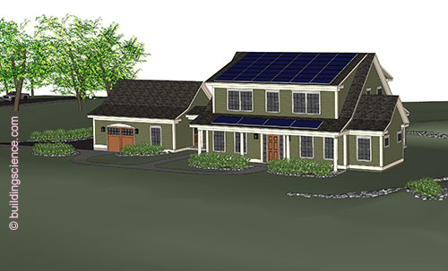
Figure 5: 3-D Rendering of NZERTF from SSE
3.1.3.1 Exterior Design
In this section, general design decisions about the exterior that were made specifically to address energy efficiency and/or durability of the house are described.
House Form and Orientation
The relatively compact footprint and volume of the house contributes to energy efficiency primarily because of a low surface area to volume ratio. Even though this type of house can accommodate nearly a full second floor, the roof configuration lowers the overall profile of the house and reduces the exposed wall surface area.
With solar energy as the renewable energy source, a south-facing sloped surface is needed on which photovoltaic panels can be mounted. The 4:12 sloped roof of the shed dormer across the front of the house provides a fully unshaded surface for the solar panels. The roof of the porch (also 4:12) can be used for this purpose as well. While this slope is not ideal from the perspective of optimizing solar production, it represents a typical configuration in residential construction.
The south-facing roof of the detached garage, that is located to the west side of the house, provides additional space for solar panels. For the demonstration phase, the garage roof is not to be used for photovoltaics; but should additional or alternative solar panels be needed for research purposes, the 9.5:12 sloped garage roof could be used.
Location, Type and Size of Windows
With the house placed on the site to maximize sun exposure, techniques for controlling solar heat gain were considered while determining the number, location and size of the windows. Table 1 shows the distribution of the total window area over the exterior walls.
Table 1: Exterior Window Distribution
| North | South | East | West | Total | |
| Surface area of exterior wall | 71.3 m2 (767 ft2) | 71.3 m2 (767 ft2) | 83.7 m2 (901 ft2) | 83.7 m2 (901 ft2) | 310 m2 (3,336 ft2) |
| Total area of glazing | 11.7 m2 (126 ft2) | 16.5 m2 (178 ft2) | 6.2 m2 (67 ft2) | 4.2 m2 (45 ft2) | 38.6 m2 (416 ft2) |
| % glazing of surface area | 16.4% | 23.2% | 7.4% | 5% | 12.5% |
In a mixed-humid climate, solar gain through south-facing windows can lower the heating load during the winter but increase the cooling load in the summer. The general guideline in this climate is to place south-facing windows so that they are fully blocked in the summer to prevent solar heat gain but exposed to allow solar heat gain in the winter. For the NZERTF design, there is more glazing on the south facade than on any other side. The windows on the 2nd floor and in the living area extension to the east are directly below an overhang; the depth of overhang is designed so that the summer sun at its solstice is totally blocked by the overhang whereas the winter sun at its solstice reaches the entire window. The first floor south-facing windows along the main section of the house (about 44 % of the south-facing glazing) are fully shaded in the summer by the roof of the front porch; during the winter, about 50 % of that glazing is unshaded (see Figure 6).
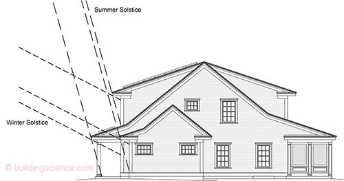
Figure 6: East Elevation with Summer & Winter Solstice
Because of the deep front porch, the full potential of solar heat gain during the winter of the first floor south-facing windows is not realized. However, the front porch provides a number of other benefits: aesthetically, the porch roof connects to the main gable roof and extends it forward from the base of the front shed dormer so that the house appears less tall when viewed from the road below; the shaded porch provides an extended living space during temperate weather; and the porch roof provides additional south-facing roof area for installation of solar panels. Since the house design only has a minimal amount of interior surfaces with thermal mass (mainly tile and drywall) a tradeoff was made in favor of the benefits provided by the porch roof versus the maximum solar heat gain that could be obtained in the winter through the four first floor front windows at the porch.
Sunlight coming in through the glazing on the east and west contributes to the passive solar gain of the building enclosure during the winter; unshaded east and west facing glazing adds to the cooling load with unwanted solar heat gain during the summer. For the east and west sides, glazing is only about 7.4 % and 5 % respectively of the surface area. Windows on the north side contribute to the heating load during the winter because of the relatively low thermal resistance of glazing. About 16.4 % of the north facing wall is glazing but nearly one-third of that is the patio door leading to the screen porch and thus is somewhat protected from exterior conditions. This conservative use of glazing is consistent with the style of the house and the low energy use goal but is sufficient to provide natural lighting and ventilation for the interior where needed as is described later.
All windows are double hung except where interior or exterior conditions require a shortened window in which case awning windows were specified. One low energy use strategy would have been to use only casement and awning windows since these are generally more airtight than double hung windows. This approach was not used for the NZERTF since that would not be typical for a house of this style.
3.1.3.2 Interior Design
This section describes general interior house design decisions that were made specifically to address energy efficiency of the house.
Room Layout and Window Distribution
The main section of the floor plan of the NZERTF is approximately square. The living spaces and bedrooms were placed in corners of the plan with the circulation occurring in the center (see Figure 7). With this layout, all rooms have windows on at least two adjacent sides. Since all windows are operable, this supports the use of natural ventilation as an option both within the individual rooms and, if room doors are open, for the entire house when the weather is appropriate. An advantage of a double hung window is that airflow can come from the bottom or the top. Lowering the top sash allows for natural ventilation while still providing privacy.
The window arrangement also provides daylighting in the living areas throughout the day. In the second floor bedrooms, most of the daylighting is provided by the north- or south-facing windows because the east or west windows are located in alcoves which limit the range of the natural light.
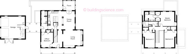
Figure 7: First Floor (left) and Second Floor (right) Plans
It was a tradition in old New England houses that the front of the house face south and the kitchen, as a source of heat, be on the north; with this arrangement the kitchen augments the heat in the winter and avoids overheating in the summer.16 While modern kitchen appliances minimize this effect, there is still some validity to this reason for placing the kitchen on the north side. But more beneficially, with this location the kitchen has the best natural lighting because light from the north does not produce glare and is even throughout the day.
The layout of the house was arranged so that all bathrooms, the kitchen and the laundry are in the same quadrant of the house – the northwest quadrant. Since the hot water heater is also located in the northwest quadrant of the basement, this simplifies the plumbing and minimizes the length (and heat loss) of the water lines.
Conditioned Attic and Basement
Since both the attic and the basement were to contain mechanical equipment, they were both included in the conditioned space. Heating, cooling, ventilation, and hot water equipment as well as ductwork are located in the basement. The inverters for the solar panels and some ductwork are located in the attic. The basement is actively conditioned with supply diffusers whereas the attic is conditioned through transfer vents between the 2nd floor and the attic.
Built-in Chases for Ducts
To support future research efforts, a large amount of ductwork must run between the basement and rest of the house. To provide space for vertical ductwork, the interior design included several chases integrated as design elements. Thickened walls were designed between the entry hall and the living room, between the entry hall and the back of the house, and between the living room and the dining area to create formal entries to the spaces while providing ductwork chases from the basement to the 2nd floor. Similarly, two “columns” on either end of a room divider between the kitchen and the dining area function as chases up to the 2nd floor. There is also a hidden chase connecting the basement to the attic through “dead space” behind the hall walls on the first and second floors.
In addition to the chases, the wall between the kitchen and the 1st floor bathroom was widened to a 38 mm x 140 mm (2x6) partition to provide more space for ductwork and plumbing in that wall.
3.1.4 Additional special requirements
In many ways, the NZERTF was designed as a typical net-zero energy capable house. However there were some additional requirements that required special attention during design as described in this section.
3.1.4.1 Accessibility
The house was designed so that all entrances and all movement through the first floor are barrier- free based on the Uniform Federal Accessibility Standards (UFAS) (Code of Federal Regulations, 1997) and so that the first floor bathroom is accessible. In addition, access to the garage was designed to be barrier free.
Both the staircase to the basement and the main interior staircase were designed to be wide enough and to have adequate wall support for future stair lifts. To permit access to the stair lift to the basement, the opening at the top of the basement stair would need to be widened to the full width of the basement staircase. Also, the closet at the top of the main staircase would need to be opened to provide a storage place for the stair lift when not in use. Since these openings are within a bearing wall, the structure was designed to span across them so that this adaptation can be made in the future without requiring structural changes.
3.1.4.2 Support for research
In addition to the systems installed for use during the demonstration phase, support was provided for future systems including duplicate ductwork for the central air system run-outs for an alternative air distribution system; ductwork for a future ducted 2-1 multi-split system; tubing for future radiant floor heating in the basement slab; capability for two central air handlers to be in place concurrently. Also, ductwork for a future high velocity cooling system was installed using a design provided by NIST.
The design of the electrical system was required to provide several independent systems – one for normal household use only, one for garage use, and one for instrumentation and monitoring. Only electricity for normal household use is subject to the net-zero energy use requirement.
3.1.4.3 Made in USA
Because the construction costs were funded by ARRA, a “Buy American” provision applied to the project. NIST’s implementation of this provision required that all products delivered to the site have documented proof that they were manufactured in the U.S. Exceptions to this requirement were allowed only if it could be demonstrated that no U.S.-made product could be substituted and still deliver the function and energy use parameters required to meet the net-zero energy goal.
3.1.4.4 LEED for Homes Certification
The building was to be LEED Certified under the LEED for Homes 2008 standard. During the design phase, it was determined that LEED for Homes Platinum would be achievable. This added certain requirements that were not related to the net-zero energy goal, but contribute to sustainable practice.
3.1.4.5 NIST-provided Indoor Air Quality (IAQ) Specification
As part of the NIST research effort associated with the NZERTF performance, the indoor air will be monitored for volatile organic compounds (VOC) and aldehyde levels. In support of this effort, specific restrictions were provided by NIST for the contents of products used in the building’s construction. The products to which these restrictions applied include structural wood products, adhesives and sealants, interior wood-based products, interior paints and other coatings, interior-side insulation, cabinetry and wallboard. These restrictions were stricter and more specific than those in LEED for Homes.
3.2 Structure Design Decisions for Net Zero Goal
The structure for the NZERTF is typical of conventional construction but there were several structural design decisions made specifically to improve energy efficiency or to support a specific NZERTF requirement. These are described in the following sections.
3.2.1 Advanced Framing
The framing uses an approach often referred to as “advanced framing.”17 This technique replaces
the standard 406 mm (16 in.) on center (o.c.) 38 mm x 89 mm (2x4) or 38 mm x 140 mm (2x6) construction with 38 mm x 140 mm (2x6) framing at 610 mm (24 in.) o.c. along with single top plates, 2-stud corners, single headers in bearing walls, no headers in non-bearing walls, no blocking at partition walls, no jack studs and no cripples. Rafters and floor joists are also installed at 610 mm (24 in.) o.c. rather than the standard 406 mm (16 in.) o.c. Use of advanced framing reduces the amount of wood that is required and increases the volume of cavity space so that more cavity insulation can be installed. For the NZERTF, all interior partitions, as well as the center east-west load-bearing wall, were also framed at 610 mm (24 in.) o.c. This provides slightly more space within the interior walls that can be used for ductwork or other equipment.
For some implementations of advanced framing, the exterior plywood or oriented strand board (OSB) sheathing of standard construction is also eliminated except where required as shear panels. However, for the NZERTF, plywood sheathing was applied to all of the framing. Because of the wind exposure design criteria for the NZERTF site, the wall sheathing is needed to resist the roof uplift. Since plywood is not available in sheets that are long enough to span from the sole plate to the top plate, horizontal blocking was added to the wall framing where needed to secure the ends of the plywood sheets as required to resist the uplift.
Wall framing elevations for all exterior walls and for the interior bearing wall were developed during design and included in the NZERTF construction set. These elevations show the location and size of every framing element and sheathing panel and indicate the size of the header in those places where a header is needed. Also included in the construction set are 3-dimensional drawings showing the advanced framing details. The details for the 2-stud corners and the termination of partition walls demonstrate the use of drywall clips to attach the interior gypsum wallboard (see Figure 8).
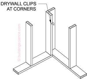
Figure 8: Advaced Framing: Bottom of 2-Stud Corner (from Construction Set)
While 610 mm (24 in.) o.c. framing is acceptable for supporting interior gypsum wallboard, it is preferable to have 406 mm (16 in.) o.c. support for tile backer board because of the potential weight of the tile. For the NZERTF, 406 mm (16 in.) o.c. interior-side horizontal ladder blocking was added to the exterior wall framing in those areas where there was to be tile on the interior.
3.2.2 Open-Web Floor Trusses
To accommodate the layout of the ductwork, as well as to make it easier to add cabling and wiring in the future, 356 mm (14 in.) deep open-web wood trusses were specified for the 1st and 2nd floor joists. Several removable access panels were called for in the 1st floor ceiling and on the 2nd floor (in closet floors) so that the NIST researchers would have access to the space below the floor. The basement ceiling trusses are left exposed for the same purpose.
For complete report, download complete .pdf
Footnotes:
- http://www.eere.energy_gov/buildings/building_america
- Lukachko (2011)
- Brown, Richard et al (2006)
- Ueno, K. et al (2013)
- Torcellini, P. et al (2006)
- Ueno, K. and Straube, J. (2010)
- Straube, J. (2008)
- Building Science Corporation (2009a)
- Building Science Corporation (2013)
- http://www.epa.gov/radon/pdfs/buildradonout.pdf
- Building Science Corporation (2009b)
- Lstiburek, J. (2008a)
- U.S. Department of Energy, “Installing and Maintaining a Home Solar Electric System” http://energy.gov/energysaver/articles/installing-and-maintaining-home-solar-electric-system. Last accessed August 26, 2014.
- Building Science Corporation (2010a)
- Building Science Corporation (2009c)
- Brown, G.Z. and DeKay, Mark (2001), p. 145.
- Lstiburek, J. (2010).