This paper documents the experimental methodology, details, and results and discusses how this information can be applied to modeling drained wall systems. Practical applications and research questions arising from the work are presented. Drainage is widely accepted as one of the most effective measures for reducing moisture damage due to rain penetration. Although drainage is effective, some water is always retained in the drainage space, either as droplets on the surface or absorbed and adsorbed to materials lining the drainage space. Previous ASHRAE-sponsored research has shown that ventilation behind the cladding can remove significant amounts of this retained moisture.
Introduction
Drained wall systems are widely recommended as the best strategy for controlling rain penetration (Ritchie 1961, CMHC 1999, Lstiburek 2006). However, gaps behind cladding also can be used to encourage ventilation drying and to allow for construction tolerances of the cladding relative to its substructure. Although drainage is an effective means of rain control, the width of the gap required to allow drainage, and the rate of drainage required is still a matter of practical debate and research. It is also clear that drainage will not remove all the water that penetrates the cladding – some water is always retained on the drainage surfaces. Both these issues are the subject of the research reported in this paper.
Background
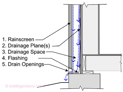
Moisture in buildings is one of the leading causes of building enclosure failure. For moisture damage to occur four conditions must be met: moisture availability, a driving force, a path, and a material that is moisture susceptible at the temperature conditions. Moisture damage will only occur when these four conditions are met, and the safe storage capacity of a material is exceeded. Some materials (such as concrete) can store much larger amounts of moisture for longer periods of time than other materials (such as paper-facings) before their safe storage capacity is exceeded and a problem results. It has been recognized for many years that using a drained approach to controlling rain penetration will often provide better control than other strategies such as perfect barrier and mass walls (Ritchie 1961, Lacasse et al 2003). A functional drained wall system is comprised of five critical components (Figure 1):
- a rainscreen (a cladding that acts as a screen to rain, sun, impact, fire and more),
- a drainage plane (a capillary break that resists the inward movement of liquid water),
- a drainage gap or cavity.
- a flashing system to direct vertically drained water horizontally out, and
- weep or drain holes to allow water to pass back out through the cladding.
Figure 1: Components of a Functional Drained Wall System
The role of the gap is to relieve the potential buildup of hydrostatic pressure due to gravity drainage of liquid water. If the gap is large enough, airflow through the gap can also allow ventilation and drying.
If liquid water penetrates the cladding some water will be stored even in a wall system with excellent drainage: water can be trapped in undrained depressions/obstructions in the wall system, on surfaces by surface tension, and/or absorbed into most building materials by capillarity. The only one of these storage mechanisms that is time-dependent is capillarity: water is wicked into an absorbent material at a decreasing rate as time progresses. Water vapour can also become adsorbed into building materials, or may be present in the air cavities in the enclosure. All of these mechanisms act to ensure that all water that penetrates the cladding is not drained. Hence to avoid moisture problems, some drying should be provided. (Straube & Burnett 1998).
Depending on the type of storage, several mechanisms are available for drying (Figure 2). Undrained moisture can be removed from the drainage gap by ventilation or diffusion. Moisture stored in the wall materials may also be able to move to exterior surfaces by capillarity and then be removed by evaporation.
Figure 2: Wall System Drying Mechanisms (Straube & Burnett 2005)
Enclosure assemblies with a gap sufficiently large to allow gravity drainage are termed drained systems, and such assemblies with gaps sufficiently large to allow ventilation drying are termed “drained and ventilated systems. Although a drainage gap has been accepted as an effective means of handling liquid water penetration through the screen, and ventilation drying shown to be a potentially effective drying mechanism (Straube et al 2004), very little research has been undertaken to define the minimum or optimal gap size required for either drainage or ventilation drying.
Previous Research
Several recent research projects have investigated drainage and ventilation drying. Some are reviewed below.
An experimental study of drainage in small gaps behind cladding was previously conducted together with Oak Ridge National Labs and Building Science Corporation (Straube et al 2000). This study was limited to vinyl siding and stucco on various sheathing membranes. The experiments determined the drainage capability by applying water to the face of the cladding as a spray or poured into the top edge of the wall behind the cladding.
It was found that water that passed through joints and penetrations in the vinyl siding drained and was caught in the horizontal edges and directed laterally to the j-trim where it drained vertically. It was concluded that significant areas of the drainage plane were not wetted with either water application method. This conclusion was subsequently visually confirmed when 12’wide x 6’ high samples of horizontal vinyl lap siding were tested when installed over a transparent plexiglass drainage plane.
The stucco wall assemblies were tested by pouring two litres of water behind the cladding. It was found that single layers of sheathing membrane bonded to the stucco and hence did not allow good drainage (as there was no gap). By adding an extra layer of sheathing membrane as a bond break, water drained well even though the gap was very small (under 1 mm) and discontinuous). Even corrugated polymeric housewrap performed poorly when installed directly behind stucco because of the bond formed, but the corrugated housewrap in combination with a felt paper bond break provided the fastest drainage of all walls tested.
We also previously investigated ventilation drying in wood frame walls together with Penn State University and Oak Ridge National Labs (Schumacher et al 2003). An experimental wall was wetted and then dried while resting on a load cell to constantly measure the changes in mass of the wall. A counterbalance was used to offset the dead load on the load cell and thereby greatly increasing the precision of the readings. This research demonstrated that larger gaps allowed for faster ventilation drying.
Research led by Onysko (2006) at Forintek investigated drainage and moisture retention behind EIF systems installed over trowel applied membranes. Their experimental approach injected small amounts of rain onto the drainage plane over several hours. They found that all injected water was not drained even when very hydrophobic drainage planes were used.
To better understand the required drainage capacity of a drainage gap, a driving rain and wind analysis was conducted using extensive Canadian weather data (Straube & Schumacher 2006). It was found that the driving rain deposition rate for an average driving rain event for all monitored Canadian cities was 0.7 mm/hr (0.012 l/m2-min). For the extreme rain event, the 1% rain event (that is the rate us exceeded 1% of the hours during rain) was chosen. The limiting values for the 1% driving rain event ranged from 3.0 mm/hr (0.05 l/m2-min) and 10.4 mm/hr (0.17 l/m2-min) depending on the city studied
The calculated driving rain rates and wind pressures were compared to two water penetration test standards: ASTM E514 Standard Test Method for Water Penetration and Leakage Through Masonry, ASTM E331 Standard Test Method for Water Penetration of Exterior Windows, Skylights, Doors, and Curtain Walls by Uniform Static Air Pressure Difference (Table 1). It can be seen that the testing standards imposed loads that are many times, often orders of magnitude, higher than even the most extreme rain event recorded in Canadian data. Although the peak driving rain rates are likely higher in hurricane regions, they are unlikely to be more than ten times those of the rainy regions of Canada.
Research Scope and Objectives
A research program was developed with two main objectives. The first objective was to determine the gap width that would allow for drainage. The other main objective was to develop a repeatable and defendable test method to characterize the drainage, storage and drying of drained wall systems. The scope of the research was limited to lighweight claddings with relatively small gaps and spunbonded polyolefin (SBPO), building paper, and trowel-applied sheathing membranes.
Methodology
From the previously-cited research at PSU and Forintek, it was clear that the temperature and RH conditions surrounding the test apparatus needed to be tightly controlled to avoid variations due to adsorption and to ensure repeatable drying rates. Hence, tests were conducted in the Building Engineering Group laboratory which is operated at target conditions of 20°C and 50%.
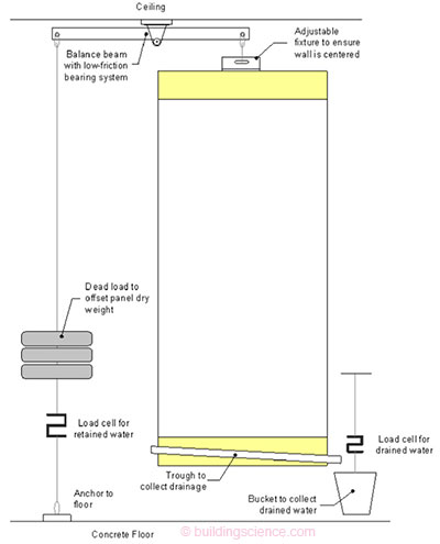
A test apparatus capable of accepting walls weighing several hundred kg and resolving mass changes to several grams was constructed. The load cell was installed in tension to remove all lateral forces (Figure 3). Before each test, calibration weights were added to confirm the linear response of the system, and to calibrate its output. The amount of water drained from the system could also be measured gravimetrically using this apparatus.
Figure 3: Wall Balance Testing Apparatus
Drainage Test Protocol
Based on ASTM E2273, we originally chose 8 liters of water as the volume to be poured behind the cladding in two doses. However, during the first tests it was noted that the amount stored in the wall reached almost the same maximum value even if a dose much smaller than 4 liters was used. In subsequent testing we chose to impose two doses of 1.5 liters for a 4’ wide (1.2 m) x 7’ (2.1 m) tall wall system, and two doses of 1.0 liter for smaller 3’x6’ (0.9m by 1.8m) specimens. In all cases drainage stopped within one to two minutes after water was no longer added to the drainage gap. Note that the maximum stored is defined here as the short-term storage quantity. Many materials can absorb much more moisture if the wetting is continued for much longer than the 1 minute test. However, the test protocol is not intended to measure the capillary uptake rates and sorption storage . . .
Download complete report here.


