One of the most difficult buildings to build is a building with a swimming pool because–wait for it–there is a swimming pool inside. It gets even worse when the pool is in a ski resort on a mountaintop (Photograph 1). Ah, I love the rich people and their problems.
Or, even better, let’s make it a recreation center in the middle of North Dakota that has a limited construction budget. We are always asked to deal with recreation centers with swimming pools and no budget. How about an indoor water park attached to an ugly hotel? The problem is pretty much the same whether you are in the middle of Ohio in a hotel with an indoor pool, a ski resort recreation center in the middle of Colorado, an indoor water park in the middle of Wisconsin or in a rich guy or girl’s house in Whistler, B.C., or pretty much anywhere.
Pick an extreme external climate and add an extreme internal climate. And then, if you are really unlucky, involve a famous architect.2
The problem is fundamentally pretty straightforward. We have a huge internal moisture load that, for once, you cannot blame on your mechanical engineer or HVAC contractor. There’s a pool filled with water in your building for Pete’s sake.3 You can’t dehumidify your way out of the problem; you can’t ventilate your way out of the problem. You can localize the problem by depressurizing the pool area relative to adjacent spaces or by pressurizing a boundary space between the pool area and adjacent areas, but, in the pool area, you are pretty much toast.
I am tired of being told that there would be no problems if the pool had a cover or if the pool water temperature was kept colder. What is the point of having an indoor pool if it is too cold to use, and if you have a cover on it all the time? You may as well take a bath, and call it a day. Sheesh. All of these things–ventilation, dehumidification, depressurization, water temperature control and the use of a pool cover–reduce the load on the enclosure, but even all of them together won’t avoid problems without a good enclosure.
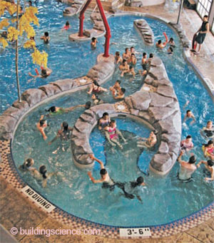
Photograph 1: If Only They Knew–Happy folks getting wet while someone else gets a financial bath. It is not easy keeping the roof and walls dry when everything else is wet.
Let’s assume that the pool area is under a positive pressure, the air in the pool area is 80°F (27°C) and the relative humidity is 70%. I call that “80 – 70 air” and you had better design the building enclosure to deal with it.
What are the outside conditions? To be safe, assume really, really cold in the winter and hot and humid in the summer. Pretend that your building is in International Falls, Minn., during the winter, and then assume it magically moves to Atlanta in the summer. If you can pull that off, you are pretty much in the clear.
We need to be perfect. And the only wall that will work, of course, is “the perfect wall.” We have been here before.4 Put the water control layer, the air control layer, the vapor control layer and the thermal control layer on the outside of the structure. Put everything else inside, especially the services. Same for the roof. Done.
Here is the secret–the control layers need to be continuous–especially the air control layer. If you don’t have air moving across your wall or roof assembly, not much bad can happen. Check out Figure 1 for a conceptual description of the simplest design solution. The bold line represents the air control layer. The shaded layer represents the thermal control layer. The dotted line represents a ventilated cladding. The roof is a vented attic. Classic, simple stuff. Any bad stuff from inside that gets past the bold line and gets into the shaded stuff can pass right on through and get to the outside through the dotted line and the big sloped hat with holes. You don’t need a computer simulation to understand this. You don’t even need a psychrometric chart.
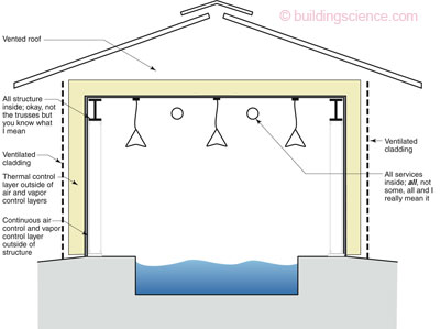
Figure 1: Simplest Design Solution–The bold line represents the air control and vapor control layers. The shaded layer represents the thermal control layer. The dotted line represents a ventilated cladding. The roof is a vented attic. Classic, simple stuff. Any bad stuff from inside that gets past the bold line and gets into the shaded stuff can pass right on through and get to the outside through the dotted line and the big sloped hat with the holes.
A few little tricks of the trade–think of cladding as a dehumidifier that sucks moisture out of the shaded stuff. That means the back of the cladding will get wet if there is a flaw in your wall. What are the odds of there being a flaw or less than perfect workmanship? If I were using wood cladding, I would not just back ventilate it, I would back-coat it with primer and paint. Just like the old guys used to. I do not want the wood to absorb water. If it does, it can leach tannins and other water-soluble extractives. Ask me how I know?
If it is cement siding, you had better coat it on the backside, as well as ventilate it. If you have brick, you had better ventilate the heck out of the space. If it is metal, you had better think a lot about stainless steel and magic pookey to protect it, as well as good cladding ventilation. If there is a flaw and air gets out, the air is going to be carrying more than just water vapor: chlorine, bromine and other aggressive oxidizing (a.k.a. corrosive) agents. You ever see what they put into the water? It will eat your insides out and the insides of your wall assembly as well.
A few more tricks to remember. The vapor drive is extreme in the extreme. Use membranes on the outside of the sheathing that are vapor closed. Use the fully adhered stuff that needs primers and some old guy with an attitude watching it going up. Yes, it sounds like a throw back to an ancient time, the 1970s. But pools are nasty business.
I don’t care that much about the insulation that goes outside of the air control and vapor control layer. They all work. All of them. Just put in more than you think you need, and don’t screw up the insulation with thermal bridge cladding attachments. Cladding is not very heavy. You are not holding up a bridge or hanging an SUV from the wall.
Metal hat channels over the insulation or furring strips over the insulation work just fine. Do not, and I repeat, do not run a continuous metal z-section back to your metal stud wall or condensation will form on the inside during cold weather. It is a huge thermal bridge. If your structural engineer says you have to do it, get yourself another structural engineer. Lots are available. Get an old one. They know stuff.
What about air conditioning? What about it? With the vapor control layer on the outside of the structure, it does not matter if condensation happens on the outside of this outside layer because, wait for it, it is outside. But, won’t the insulation layer get wet? Give me a break. The water will drain; it will evaporate; it will not degrade any of the insulations enough to allow us to even measure the degradation accurately. You want to worry about thermal performance? Don’t screw up the cladding attachment. See what I just said about thermal bridges. That is where the action is.
We done with walls yet? Not quite. No vapor barrier on the inside lining. No vinyl wall covering. And, for the love of Pete, no insulation in the studs. That space is reserved exclusively for services. Memo to interior designers: think about picking materials that are not affected by water for your interior finishes. But, when you pick them, make sure they are vapor open. Vapor open paints on vapor open interior sheathings.
A brutally simple wall roof design is presented in Figure 2. Note how we use wood as a thermal break between the trusses and the perimeter structural support. Wood is also used as “furring” to provide a thermal break between the gypsum board ceiling and the bottom chord of the truss. Steel is 300 times more conductive than wood, which is why we never see wood wiring and wood frying pans.
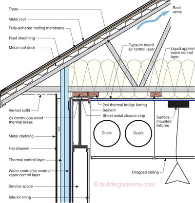
Figure 2: Brutally Simple Wall Roof Design–Note how we use wood as a thermal break between the trusses and the perimeter structural supporting steel beams. Wood is also used as “furring” to provide a further thermal break between the gypsum board ceiling and the bottom chord of the steel truss. The key to this detail is the sheet metal closure strip that provides air control layer continuity and vapor control layer continuity between the air control layer of the attic assembly and the air control layer of the wall assembly. Ditto for the vapor control layers. You install the sheet metal closure before you set the wood thermal break and before you set your trusses. The sheet metal provides a strip to connect your attic air control layer to. Gypsum board makes a great air control layer. Terminate the edge of the gypsum board ceiling in a “drywall return” and leave a gap to squirt sealant into. Bend the sheet metal closure down over the exterior gypsum sheathing and connect your wall assembly air control layer membrane to the sheet metal strip.
In Figure 2, the key to this detail is the sheet metal closure strip that provides air control layer continuity and vapor control layer continuity between the air control layer of the attic assembly and the air control layer of the wall assembly. Ditto for the vapor control layers. You install the sheet metal closure before you set your trusses. The sheet metal provides a strip to connect your attic air control layer to. Gypsum board makes a great air control layer. Terminate the edge of the gypsum board ceiling in a “drywall return” and leave a gap to squirt sealant into. Bend the sheet metal closure down over the exterior gypsum sheathing and connect your wall assembly air control layer membrane to the sheet metal strip. This also provides closure and continuity for the vapor control layer.
Notice in Figure 2 that the exterior rigid insulation extends up around the roof trusses to provide a “baffle” to control wind washing. Make sure the truss is deep enough over the perimeter structure so as not to squeeze the ceiling thermal layer and make it too thin.
Also, notice the dropped ceiling for the ducts and lights and sound stuff. All of that junk is inside the ceiling gypsum board air control layer.
Finally, on Figure 2, notice that the airtightness of the ceiling gypsum board is the single most important thing in this approach. Having said that, we also need some vapor control. In Climate Zones 2 through 4, use a liquid-applied vapor control layer yielding a Class III rating (something between 1 and 10 perms wet cup). In Climate Zone 5 continue to use the liquid, but go to Class II. If you are in Climate Zone 6 and higher, go to Class I and consider a foil-backed gypsum. Stay away from that sheet polyethylene junk because it is a nightmare to install. Stick with something that sticks to the gypsum board: either a coating on the inside, or a foil-facing stuck on the topside.
In all of these assemblies, insulate the attic ceiling with lots of insulation. Start at R-30 in the South. Hit R-50 when you get to Climate Zone 5. And, go up from there for Climate Zones 7 and 8.
We are not done yet with Figure 2. Ventilate this puppy. Use continuous soffit vents and lots of upper vents for the attic. When you get into high snow load areas, you can’t use ridge vents, which is why Pete invented gable vents and monitors and dormers and cupolas.
What if I don’t want to do a classic vented attic? I can’t lie to you. It gets ugly. Let’s kick up the ugliness in stages.
Let’s say you want a cathedralized roof assembly over your pool. OK, I can see that happening. Go with the approach in Figure 3. The roof cladding is still ventilated. Keep your structure to the inside of the air control and vapor control layers. The intermediate cladding is a layer of plywood, which is vapor semipermeable, and it is covered with a vapor permeable roofing membrane (a.k.a. “tar paper”), or one of those new fancy-dancy liquid-applied vapor open membranes (don’t forget to seal the joints in the plywood for more air control redundancy). Remember, that you absolutely have to over-roof one of these things with a vented roof. And, we have already beaten to death the roof-to-wall connection. They love these roofs in snow country, so don’t forget the cupolas to provide the upper roof vents that will not get blocked with all that snow.

Figure 3: Sloped Cathedralized Vented Compact Roof– The roof cladding is still ventilated. Keep your structure to the inside of the air control and vapor control layers. The intermediate cladding is a layer of plywood, which is vapor semipermeable and it is covered with a vapor permeable roofing membrane (a.k.a. “tar paper”) or one of those new fancy-dancy liquid-applied vapor open membranes (don’t forget to seal the joints in the plywood for more air control redundancy.
Next stage of ugliness. Flat roofs. Can’t we just say no? Please? Yeah, right. OK, here we go. Check out Figure 4. Note the fully adhered air control layer and vapor control layer on the paperless gypsum sheathing. Note the multiple layers of rigid insulation with the joints staggered. Note the fully adhered roofing membrane on the fiberboard hygric buffer.5 Unfortunately, also note the long screws that connect the upper membrane to the structure.
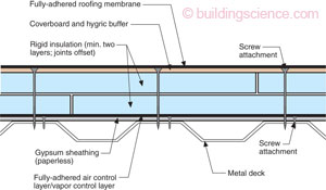
Figure 4: Flat Roof– Note the fully-adhered air control layer and vapor control layer on the paperless gypsum sheathing. Note the multiple layers of rigid insulation with the joints staggered. Note the fully-adhered roofing membrane on the fiberboard hygric buffer. Unfortunately, also note the long screws that connect the upper membrane to the structure.
In the old days, we could do this with each layer being fully adhered. But, alas, the insurance industry said no to that practice due to blow-off failures. Fully adhered once meant fully adhered, but then when the continuous supervision stopped, so did the fully adhered thing. It is easier to count fasteners than to actually know if the gooey smelly stuff was placed in the right amounts at the right temperature in the right places. The screws are both a thermal bridge and a moisture leak. They are a hole from the inside to the underside of the membrane. What else can I say? Figure 4 is good for Climate Zone 4 and lower if you cross your fingers and toes.
Yeah, what about Climate Zone 5 and higher? Also, make it flat. Aw, go away, you make my head hurt. You sure I can’t talk you into a nice sloped vented attic? How about a sloped cathedralized vented compact roof? No, eh? OK, but don’t say I didn’t warn you. Check out Figure 5. Pretty neat, eh?

Figure 5: Plywood Intermediate Layer in Flat Roof–Pretty neat, eh? An intermediate layer of plywood is used to break up the continuous screw thing: a sheet thermal break. Why plywood? Ah, it is not a vapor barrier, and it is a pretty darn good air control layer even with screws in it. Just don’t forget to seal the joints in this intermediate plywood layer. Do not use OSB; it does not breathe.
An intermediate layer of plywood breaks up the continuous screw thing: a sheet thermal break. Why plywood? Ah, it is not a vapor barrier, and it is a pretty darn good air control layer even with screws in it, just don’t forget to seal the joints in this intermediate plywood layer. Do not use OSB as it does not breathe.6
Now for something that you could use on a flat roof on that mountaintop ski resort. Figure 6 is Figure 5 with a vented upper roof membrane. The vent space is created with a 0.75 in. (19 mm) drainage mat. Once again, don’t forget to seal the joints in the intermediate plywood layer. The airtightness of this layer is a big deal in this assembly because of the vented space above under the roof membrane. The vent space is connected to the parapets and mini cupolas. How far apart are the vent openings? How many? How big? Guess. Don’t feel lucky about guessing? Then don’t use a flat compact roof over a swimming pool on the top of a freaking mountain. I warned you, didn’t I?

Figure 6: Flat Roof with Vented Upper Roof Membrane– The vent space is created with a 0.75 in. (19 mm) drainage mat. The vent space is connected to the parapets and mini-cupolas. How far apart and how many? Guess. Don’t forget to seal the joints in the intermediate plywood layer. The airtightness of this layer is a big deal in this assembly because of the vented space above under the roof membrane.
Footnotes:
You can imagine the fun folks had helping me pick a name for this one: “Treading Water;” “All Wet;” “Splish, Splash Taking a Financial Bath;” In Over Your Head” are a few of the runners-up.
Oops, that would make the building a museum. We will deal with museums some other time. To understand museums, think pool enclosures on steroids, but minus any common sense.
Peter is the name of one of the Apostles and it has been argued that the phrase is sometimes used as a euphemism replacing “For God’s sake.” In contemporary use “Pete” pretty much can mean anything or anyone and as such, is often found in consulting when the consultant is exasperated.
Controls membrane blisters from moisture vaporizing due to incident solar radiation. What are the odds that there might be moisture in this assembly? I mean, with this assembly being over a pool and all? Think of this as a roof assemblies’ version of concrete air entrainment.
This intermediate plywood layer trick goes way back. I first heard about this happening in the 1960’s. It probably goes back earlier than that. If anyone knows about how far this goes back, let me know. I love stuff like this. I heard about this drinking with an old guy in Minneapolis in the early 80’s who said this was a museum roof trick he had used. He was an architect and knew stuff and I was mesmerized. But I was 25 years old at the time and I did not get his name or the name of the building and I had no idea how big a deal this would one day be for me. But I remembered the idea. The good ideas always live on, not easily, but they do live on. Pass this one on.