This paper evaluates the performance of typical residential wall systems that incorporate water-resistive barriers with a range of vapor permeability. These systems included both absorbent and nonabsorbent claddings in hot-humid climates for direct comparison. This paper describes the test design, the test facility construction and installation, and the resulting data. The approach chosen was to use a real-time natural exposure test hut located in Tampa, FL where the interior conditions were controlled by point-terminated HVAC. Wall specimens were instrumented with a variety of temperature, humidity, and wood moisture content sensors for remote monitoring. In addition to natural weather exposure, the wall specimens were periodically wetted to simulate rain leakage by a water injection system.
Introduction
It is important to design wall systems that manage bulk water and moisture properly. No cladding system or installation is perfect; therefore wall systems should be designed to effectively dissipate any water penetrating the wall. It is not a question of if a wall will leak, but rather when it leaks, what the impact is on the structure. The management of water within walls is complicated by the need to balance the wetting and drying of walls (Baker 2006; Boone 2004; Derome 2010; Straube 2001). Balancing wetting and drying is especially complicated in hot-humid climates, which have a higher potential for inward vapor drive, particularly with reservoir claddings (Lstiburek 2004). Inward vapor drive in wall systems with reservoir or absorbent claddings has been reported in several studies and is of most concern in hot-humid climate conditions (French 2002; Kan and Piñon 2007).
Key elements to overall wall performance are the cladding used, the water-resistive barrier (WRB) and sheathing material properties, and vapor permeability of the interior wall. Although marketing claims have been made about the performance of materials and optimum ranges of material properties, little or no systematic testing of these wall system components has been conducted under natural ambient exposure in hot-humid climates.
In order to investigate the performance of typical wall system under these climatic conditions, a test-hut test protocol was chosen. Test huts have been used as part of other studies, most notably a series of studies using the BEGHUT at University of Waterloo (Gatland et al. 2007; Straube and Burnett 1998; Straube et. al. 2004).
Experimental Apparatus
Construction
The Relocatable Building Enclosure Test Station (RBETS) is an ongoing test program that provides long-term natural exposure of residential wall systems. The RBETS was located in Tampa, FL, to evaluate wall performance in a hot-humid climate.
The RBETS was created from a sea-land container, which allows the unit to be easily relocated. The long sides of this container were modified by cutting out spaces to install wall test specimens and outfitted with 2 in. × 4 in. studs prior to the construction of the chosen wall specimens. These sides were large enough to accommodate 16 different wall assemblies, each of which was 2 ft wide and 8 ft high. The surfaces of the container not used for wall specimens were insulated with spray foam to allow for controlled conditioning of the interior of the chamber. Figure 1 shows the installation of the stud walls in the sides of the container. The RBETS was placed in its test location in June 2006 and was orientated such that the opposing wall sections were exposed directly to the east and the west. This was done in order to take advantage of the local weather patterns. Once the unit was placed on site, construction of the wall assemblies was completed.
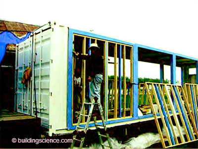
Figure 1: Installation of specimen wall framing in container.
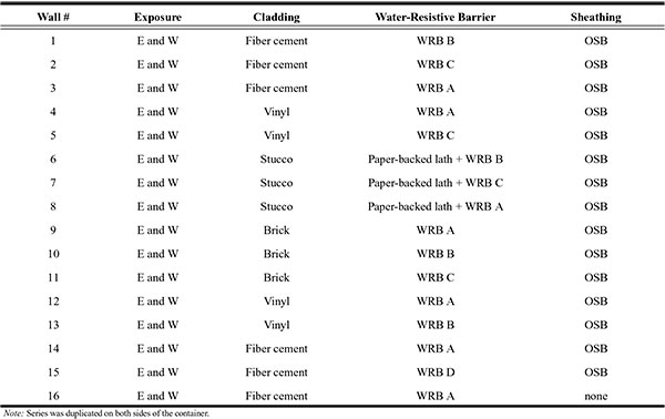
The construction of each of the wall systems took into account the local building practices. The walls were of 2 in. × 4 in. base construction. The stud space was insulated with an unfaced R-13 batt, and the interior was covered with gypsum wallboard painted with latex interior paint. In the final stage of the experiment, a vapor barrier wall covering was installed on the interior wall surface. The exterior side of 15 of the wall specimens was covered with orientated strand board (OSB) sheathing, one of four water-resistive barriers, and then one of four types of cladding. One wall specimen was an open stud wall system (no sheathing) common in the Southwest US. The four water-resistive barriers used in the testing varied by their reported vapor permeability and are listed in Table 1. The cladding types used during this phase of testing were as follows: painted fiber-cement siding, vinyl siding, brick, and stucco. Details of the wall assemblies are shown in Table 2. All wall specimens were duplicated on both sides of the container, allowing for them to be monitored with two exposures. Additionally, a limited number of wall assemblies were replicated on each side to determine specimen-to-specimen variability exposed to a single exposure. The replicated wall specimens were those with fiber-cement siding and vinyl siding each with water-resistive barrier WRB-A.
Table 1: Water-Resistive Barriers
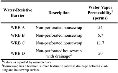
Table 2: Wall Specimen Assemblies
All of the wall assemblies were equipped with sensors that measured wood moisture content, temperature, and relative humidity. Each sensor was placed in predetermined, consistent locations within each wall assembly.
Sensors
Each wall system was broken down into layers; the innermost layer being the interior wall-board, while the outermost layer was the exterior cladding. Every layer was assigned a corresponding letter to identify its location with the wall assembly. See Table 3 for details.
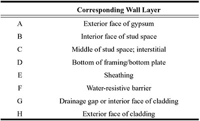
In addition to the lettering system to identify the layer location of a sensor, sensors were also placed at predetermined, consistent heights. To that end, most of the sensors were located at 48 in. from the bottom of the wall, which is the midpoint of the wall system. Others were located at the bottom or base of the wall (i.e., the base plate) and at 16 in. from the bottom of the wall. Sensors were concentrated in the bottom half of the wall, as it was expected that the highest moisture readings would occur in this region due to both the placement of the water injection apparatus at 16 in. and gravity effects. In general, each wall assembly possessed approximately 16 sensors that, combined, measured temperature, relative humidity, and moisture content. Each sensor recorded a measurement every 10 minutes that was stored on the data acquisition system as hourly averages.
Temperature Sensors. Each wall section possessed eight temperature sensors. See Figure 2 for details. The majority of these sensors were placed 48 in. from the bottom of the wall. These sensors were located on the outside of the cladding, in the drainage gap or plane, behind the OSB sheathing, in the stud space, and on the exterior face of the gypsum wallboard. This grouping of sensors allowed for a temperature profile from the interior temperature of the unit to the exterior climate to be observed (as shown in Figure 3). Two temperature sensors were also located at the base plate or bottom of the wall framing: one on the exterior face and the other on the interior face. In many cases, the readings from the temperature sensors were applied to create correction factors for the readings from the moisture wafers and pins. The error for the temperature sensors used in this study was approximately ±0.2°C.
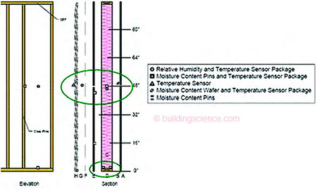
Figure 2: Location of temperature sensors.
Moisture Content: Pins and Wafers. Moisture content was measured using two different methods. The first used a small pair of nails (pins) placed in layers that contained wood (i.e., OSB sheathing, wood framing). The pins were driven into the wood substrate to a depth of approximately 1/4 in. at a spacing of approximately 1 in. apart and were often paired with a temperature sensor. When the moisture content was . . .
Download complete document here.