Improved energy efficiency building enclosures generally means an increase in R-value and reduced air leakage, which commonly reduces the drying potential of wall assemblies. Essentially, less energy is available from inside the structure to assist the transport of moisture away from the building enclosure. As energy efficiency requirements are pushing towards zero-energy structures, passive means the sun or wind become more critical approaches for achieving enhanced drying. This paper investigates the hygrothermal performance of wall assemblies with brick veneer cladding as well as manufactured adhered stone veneer with two different types of water resistive barriers.
Introduction
The demand for highly energy efficient buildings continues to rise. Improved energy efficiency of building enclosures generally means an increase in R-value and air-tightness, which commonly reduces the drying potential of wall assemblies, thus making them more vulnerable to moisture accumulation problems (Rose 2005). Essentially, less energy is available to assist the transport of moisture out of and away from the building enclosure. Under this aspect the issue of solar driven moisture that is associated with water absorptive claddings is becoming increasingly relevant: Highly energy efficient buildings with reduced drying potential of the wall cavity may not be able to sufficiently compensate for such external moisture loads when conventional moisture management approaches are being deployed. Better control of solar moisture drive and enhanced drying potential are therefore critical to ensure proper moisture management of building enclosures. As energy efficiency requirements are pushing towards zero-energy structures, passive means utilizing solar energy or wind become more critical approaches for achieving enhanced drying.
In typical applications, brick veneer is installed with a 1 in. vented or ventilated air gap between the back side of the brick and a drainage plane. Manufactured masonry veneer units are usually being deployed over a bed of lath-reinforced mortar directly over a drainage plane without a drainage or ventilation gap. The drainage plane is typically provided by a single layer of a water-resistive barrier, which acts as the second line of defense against liquid exterior moisture behind the cladding (WRB) (Bomberg et al. 2003). Numerous moisture problems and building failures have been reported when such systems are used over wood- or steel-framed walls (Rymell 2007). Next to poor detailing or building envelope designs deploying materials with low moisture tolerance (Lstiburek 2008), the lack of well-defined drainage spaces and air cavity ventilation have been implicated as reasons for these moisture problems (Karagiozis 2005).
A second layer of water-resistive barrier can provide some drainage behind the cladding, provided that the wall assembly has proper flashing and weep openings at the bottom to allow water to safely exit the space. Conversely, controlling inward solar vapor drives is more difficult. Water-resistive barriers by design are vapor permeable in order to prevent moisture from accumulating in the wall cavity. Brick veneer and manufactured masonry veneer units as well as the mortar used for installation are highly absorptive and can store significant amounts of rainwater. When solar radiation heats the cladding following rain, elevated vapor pressures occur, and the water vapor stored in the brick or masonry veneer units is being driven through the vapor permeable WRB into the sheathing and further into the stud bay, causing higher moisture contents of the exterior sheathing and wood studs. This results in condensation on interior air-conditioned surfaces. The problem is intensified in air-conditioned buildings with low-permeance vapor retarders.
A proposed solution to minimize the risk of these moisture problems is the use of a vapor-impermeable ventilated airgap membrane behind absorptive claddings. A three-dimensional polyethylene membrane will preclude inward solar moisture drive, and at the same time it allows water vapor within the wall cavity to diffuse into the ventilated air-space behind or inside the three-dimensional membrane and escape to the exterior. Hence the three-dimensional membrane allows a method of mass transfer to occur that is more effective than vapor diffusion: Air transport dries out both, the cladding and the sheathing board at the same time. An example of a three-dimensional vapor impermeable membrane with ventilated air-gap is shown in Figure 1.
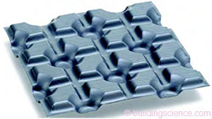
Figure 1: Impermeable three-dimensional polyethylene membrane with ventilated air-gap.
Previous research describes the effectiveness of the drying effect in such a ventilated air space (Karagiozis et al. 2005; Straube et al. 2004).
The building enclosure performance is dependent on the wall composition, as well as interior and exterior hygrothermal loads. Past work performed in a laboratory environment at the University of Waterloo by Straube and Smegal (2005) characterized the airflow, drainage behavior, water retention, and drying behavior of a three-dimensionally patterned HDPE membrane, and indicated its superior performance when compared to a #15 building paper. In the laboratory, the exterior conditions were only imposed in terms of wind pressure and solar incidence, but not in terms of actual exterior temperatures and other relevant effects, such as night-sky radiation. The study provided quantitative empirical results that allowed the comparison to standard wall types employing conventional building paper as WRB, and generated data for use in advanced hygrothermal computer models by Karagiozis (2005a).
The field tests described in this paper were initiated to show how a three-dimensional water-resistive barrier with ventilated air-cavity provides enhanced drying potential by deploying passive solar energy, and how it also provides a control layer against warm-weather inward vapor drives from highly absorptive claddings—even under severe climate conditions.
Experimental Setup
An experimental field test setup was chosen to determine and compare the hygrothermal performance of a number of different wall assemblies under various climatic conditions. Test walls with brick veneer installed outboard of a spunbonded polyolefin-based, vapor permeable water-resistive barrier were tested side-by-side in a natural exposure test facility in Charleston, SC with walls employing an impermeable three-dimensional membrane with ventilated air-cavity.
The test facility where these walls were tested is located in the city of Hollywood, SC, 21 miles from the center of the city of Charleston and 12 miles away from the Atlantic Ocean. Historical climatic data from 1961 to 1990 shows that Charleston receives an average annual precipitation of approximately 48 to 52 inches of rain (NOAA/USDA-NRCS). During the exposure time frame the exterior climate (temperature and rainfall) was within normal long term ranges, and the data monitored during the test period is representative of typical climatic conditions in that location.
In a separate setup in Waterloo, ON a series of wall assemblies was tested to compare their performance with manufactured adhered masonry veneer installed over the impermeable three-dimensional membrane in place of asphalt impregnated building paper. The average annual precipitation in Waterloo is 38 inches of rain and 58 inches of snow. During the exposure time frame the exterior climatic conditions were within normal long-term ranges in this test location also.
The field monitoring was conducted with a combination of temperature and relative humidity sensors in the drain space and the stud space, wood moisture content sensors in sheathing and framing, temperature sensors in the cladding and the drywall, and heat flux sensors located behind the interior drywall. The sensor locations in the brick walls tested in Charleston, SC is shown in Figure 2.
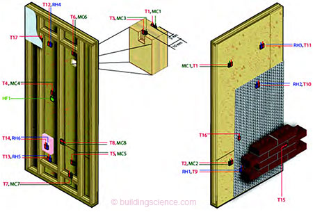
Figure 2: Typical wall setup and sensor layout for full-scale wall testing in Charleston, SC.
The sensor locations in the adhered manufactured masonry veneer walls tested in Waterloo, ON are shown in Figure 3.
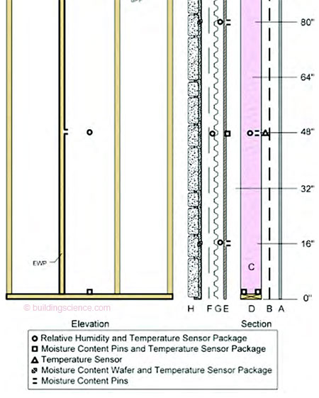
Figure 3: Typical wall setup and sensor layout for full-scale wall testing in Waterloo, ON.
The test walls were free of any penetrations to exclude the possibility for bulk water intrusion. All test panels were 8 ft in height and 4 ft in width, built with 2×6 wood frame construction with OSB sheathing, R19 fiberglass batt insulation and interior drywall finish and air barrier. The test walls at the natural exposure test facility in Waterloo, ON had an additional interior polyethylene vapor barrier, as required by the building code in this climate zone.
Monitoring of the brick walls in Charleston, SC began in June 2006 and ended in June 2007. The adhered veneer walls in Waterloo, ON were monitored from July 2007 to October 2008.
Boundary Conditions
The interior and exterior boundary conditions simulated normal conditioned spaces and were measured and recorded over the entire test period. The interior (R1 = room 1; R2 = room 2) and exterior temperatures and relative humidity for Charleston, SC are shown in Figure 4.
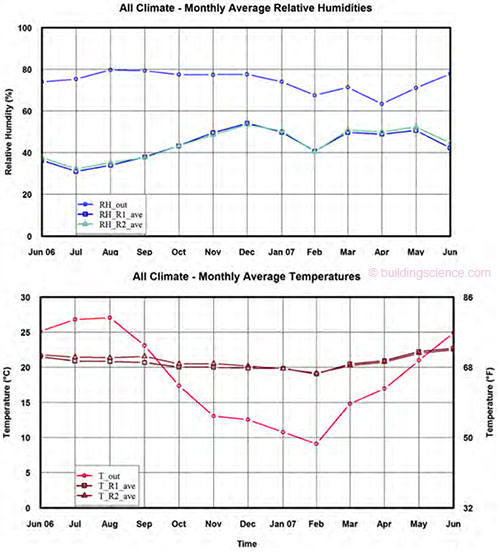
Figure 4: Interior and exterior relative humidity and temperatures during testing in Charleston, SC.
The interior and exterior temperatures and relative humidity for Waterloo, ON are shown in Figure 5. The periodic increase of relative humidity in the Waterloo testing period did not affect the hygrothermal conditions in the test walls, since these walls had continuous polyethylene vapor barriers.
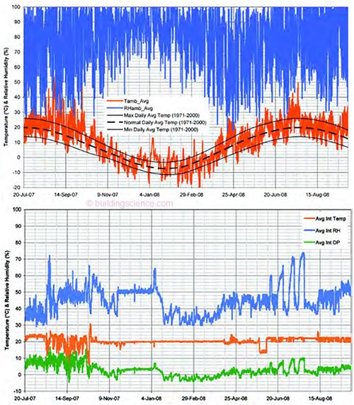
Figure 5: Interior and exterior relative humidity and temperatures during testing in Waterloo, ON.
Measurement Results and Analysis
The moisture content of the wood sheathing and framing, and the relative humidity of the stud space were analyzed to compare the hygrothermal performance of walls with and without a three-dimensional ventilated air-gap membrane.
Results from Charleston, SC
For the brick walls that were tested in Charleston, the moisture content in the wood sheathing and framing showed relatively low differences between the cases with and without air-gap membrane. However, the data shows that during several months of the year the relative humidity at the outer . . .
Download complete document here.