“Code world” is an interesting place where seemingly convoluted language is used to express simple concepts in clearly complicated ways. The reasons for this are based on “legal” principles and the desire to be “non-proprietary” even though the “proprietary” part is typically pretty obvious. So where are we going with this? Roof and wall assemblies that use materials from various manufacturers who are insanely competitive with each other – but occasionally figure out ways to work with each other where it is convenient (aka “profitable”).
Let’s lay out the actors….the rigid insulation manufacturers, the spray foam manufacturers, the fiberglass insulation manufacturers and the cellulose insulation manufacturers. It gets more convoluted…within these groups are subgroups that often engage in cage matches. You want to have some fun? Spend an evening with folks who manufacture extruded polystyrene continuous insulation sheet product sitting next to other folks who manufacture mineral wool sheet product. Sometimes these folks also hang out with folks who manufacture fiberglass cavity insulation. The folks can be from different companies….or from different corporate divisions within the same company. When they are from the same company the therapy bills are enormous. Then spend the next evening with folks who manufacture low density spray foam sitting next to other folks who manufacture high density spray foam….and yes, sometimes they are from different companies and sometimes they are from the same company. Now put all of them in the same room and try to get them to agree on how their products should work together…and then work on the code language that allows it….
The physics of how all these different materials can work with one another are typically easier than the corporate relationships and the code language allow….but to misquote that Churchill fellow[1]…what we have going on is the worst possible approach except for all the alternatives…
OK, now onto the easy part…the physics… We are going to look at “unvented attic and unvented enclosed rafter assemblies” and then we are going to look at wall assemblies.
The big deal with unvented roof assemblies is to control condensation or moisture accumulation on the underside of the roof sheathing. This can be done several ways. The first is to raise the temperature of the roof sheathing by insulating on the top of the roof sheathing (Figure 1).
If all of the insulation is on the top of the roof sheathing this is pretty much a no brainer. All of the rigid insulation board products work. Every one of them…foil faced isocyanurate, paper faced isocyanurate, extruded polystyrene, expanded polystyrene, mineral wool (aka “stone wool”), rigid fiberglass…. There are a few key points however...
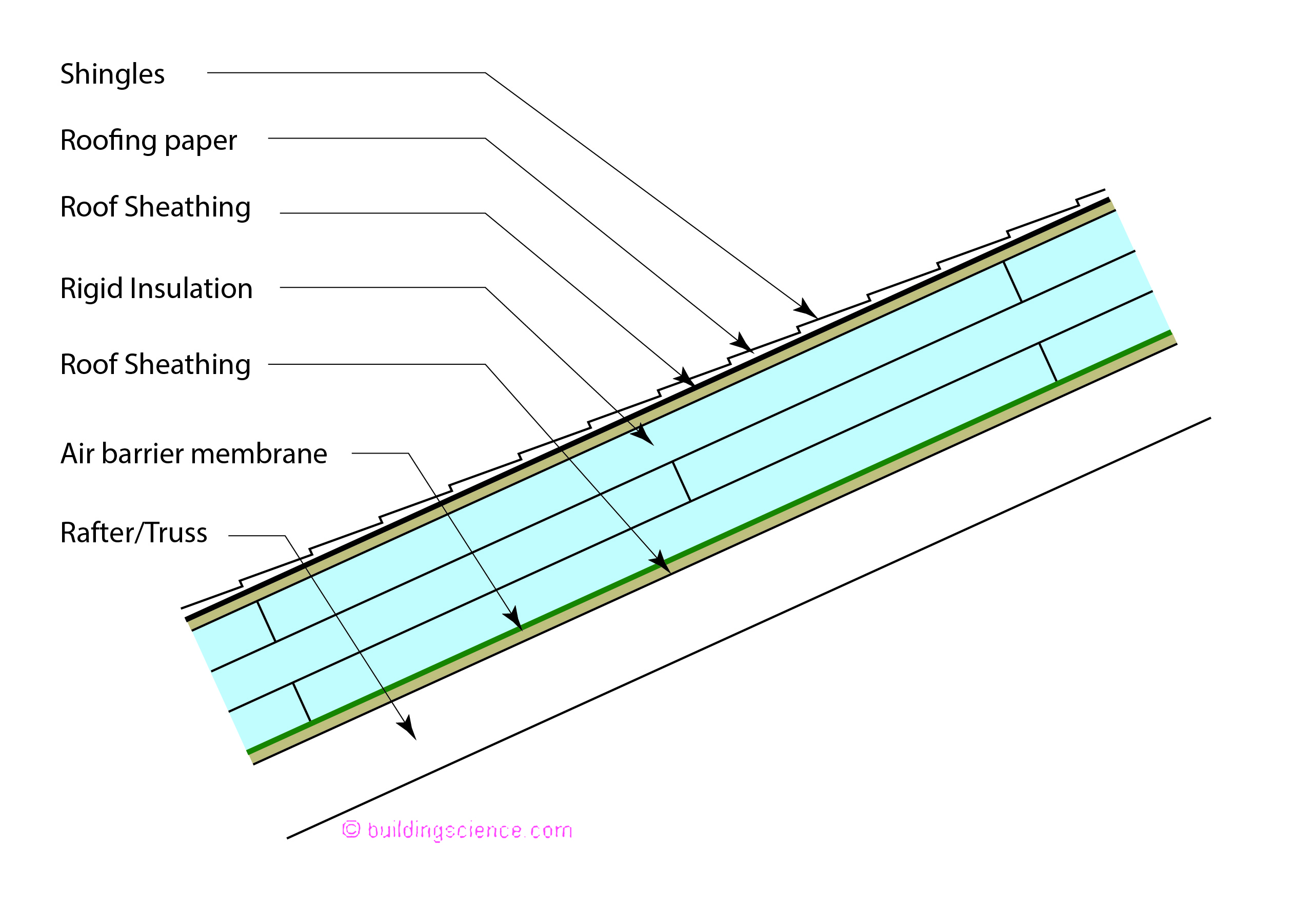
Figure 1: All Insulation Above Roof Deck - The big deal with unvented roof assemblies is to control condensation or moisture accumulation on the underside of the roof sheathing. If all of the insulation is on the top of the roof sheathing this is pretty much a no brainer. All of the rigid insulation board products work. Every one of them…foil faced isocyanurate, paper faced isocyanurate, extruded polystyrene, expanded polystyrene, mineral wool (aka “stone wool”), rigid fiberglass….
There must be an air control layer (air barrier) under the rigid insulation boards. The air control layer can be a fully adhered membrane on the roof deck or the air control layer can be the roof deck itself. Whatever. It is also a good idea to have the rigid board products installed in multiple layers with joints offset to address the inherent dimensional instability of almost all rigid board products and to limit three dimensional airflow networks within the multiple layers of this assembly (see “BSI-036: Complex 3D Airflow Networks”, February 2010).
The second way to control condensation or moisture accumulation on the underside of the roof sheathing is to limit the flow of moisture to the underside of the roof sheathing. This can be done by controlling air flow (air can transport a great deal of moisture) to the underside of the roof sheathing as well as by controlling vapor flow (molecular diffusion of water molecules typically through materials due to a concentration gradient) to the underside of the roof sheathing. The best way to do this is with spray polyurethane foam insulation (Figure 2). We have known how to do this since the 1980’s.
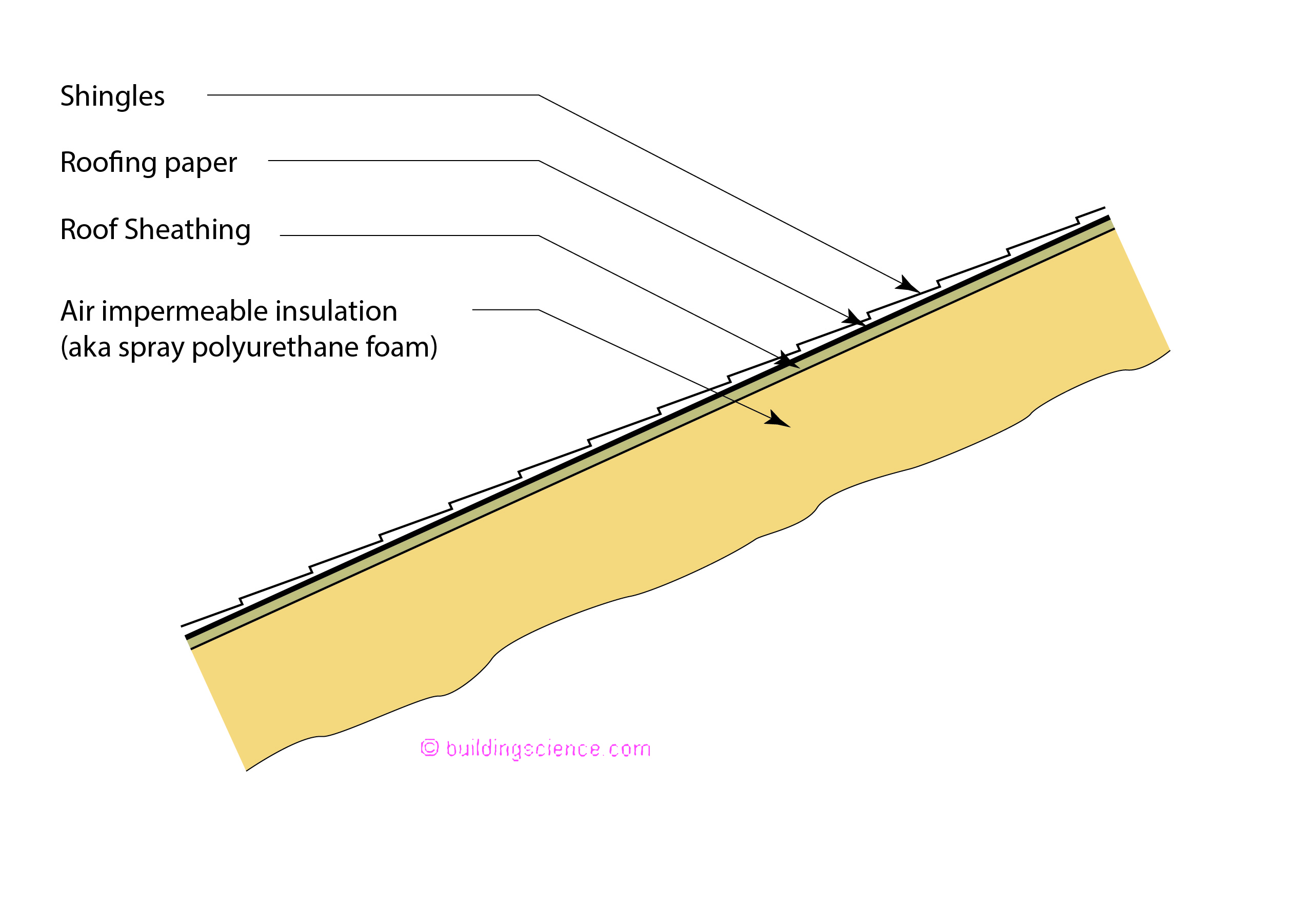
Figure 2: All Insulation Below Roof Deck - The second way to control condensation or moisture accumulation on the underside of the roof sheathing is to limit the flow of moisture to the underside of the roof sheathing. This can be done by controlling air flow (air can transport a great deal of moisture) to the underside of the roof sheathing as well as by controlling vapor flow (molecular diffusion of water molecules typically through materials due to a concentration gradient) to the underside of the roof sheathing. The best way to do this is with spray polyurethane foam insulation.
With spray polyurethane foam it is also pretty much a no brainer…except it’s not. There are two types of spray polyurethane foam[2] – “high density” (2 lb/ft3) low perm “closed cell” and low density (0.5 lb/ft3) high perm “open cell”. Both work, but both work differently. Both are good at limiting air flow but they have very different properties with respect to vapor flow.
We are going to differentiate them using the terms “closed cell” and “open cell” as the differences in molecular structure pretty much define all their respective properties and the differences between the numerous manufacturers.
Closed cell spray polyurethane foam can be used in all climate zones as it controls both air flow and vapor flow to the underside of the roof sheathing. Open cell spray polyurethane foam can only be used in warm climates and mixed climates because it is “vapor open” (high perm). In cold climates the winters are longer and too much water vapor diffuses upwards into the roof sheathing through the open cell spray polyurethane foam. The model building codes recognize this and limit open cell spray polyurethane foam to International Energy Conservation Code (IECC) Climate Zones 1 through 4 (Figure 3). Whereas closed cell spray polyurethane foam can be used in all IECC Climate Zones.
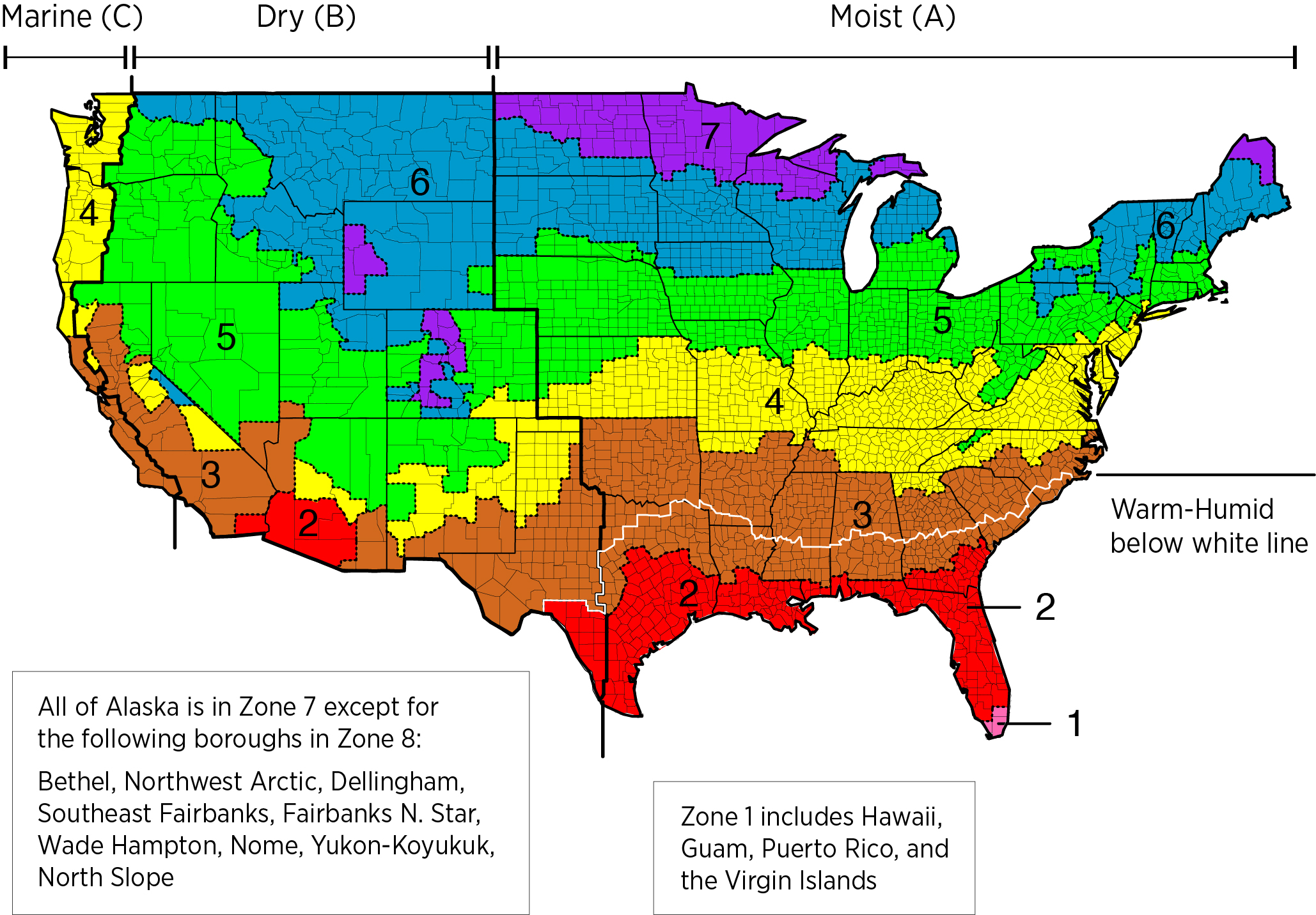
Figure 3: International Energy Conservation Code (IECC) Climate Zones
There is an additional issue with open cell SPF that we have covered before (“BSI-077: Cool Hand Luke Meets Attics”, July 2015 and “BSI-016: Ping Pong Water and the Chemical Engineer”, October 2016). Some form of moisture removal from the attic space is necessary when open cell SPF is used. The easiest way to accomplish this is with air change between the attic space and the house – provide a supply air duct that supplies 50 cfm of supply air for every 1,000 ft2 of attic area. Note that this is not an issue in hot dry climates and mixed dry climates (IECC Climate Zones 2B, 3B, 4B). Big time note…this is an issue in hot humid climates, mixed humid climates and marine climates (IECC Climate Zones 1, 2A, 3A, 4A and 4C).
Let’s now visit “code world”. As bizarre as it seems when the model codes were changed to allow the use of spray foam on the underside of roof sheathing the words “spray foam” were not allowed to be used. Huh. Too much controversy at the time. We had to “invent” a code politically acceptable word….”air impermeable insulation”. Yup. Had to define it too. That’s where 0.02 L/s-m2 @ 75 Pa came from[3]. Yes, spray foam is air impermeable. Of course other materials also are…but you get the idea of how much fun “code world” is.
So note the different approaches between Figure 1 and Figure 2. In Figure 1 all of the insulation is on the top of the roof sheathing and in Figure 2 all of the insulation is on the underside of the roof sheathing. You of course know what is coming next….some of the insulation on the top of the roof sheathing and some of the insulation on the underside of the roof sheathing (Figure 4).
This is where it gets interesting…but pretty logical. You don’t need to put all of the insulation on the top of the roof sheathing to elevate its temperature sufficiently to control condensation and moisture accumulation. You just need to put enough of it to keep the moisture content of the sheathing below 20 percent by weight[4]. How much will depend on where you are (“the climate zone”) and what is going on inside (“the interior moisture load”). The climate zone part is pretty easy…look at a map. The interior moisture load is a little more complicated as is the performance requirement and both are based on a great deal of historical experience, test house and test hut experimentation over several decades.
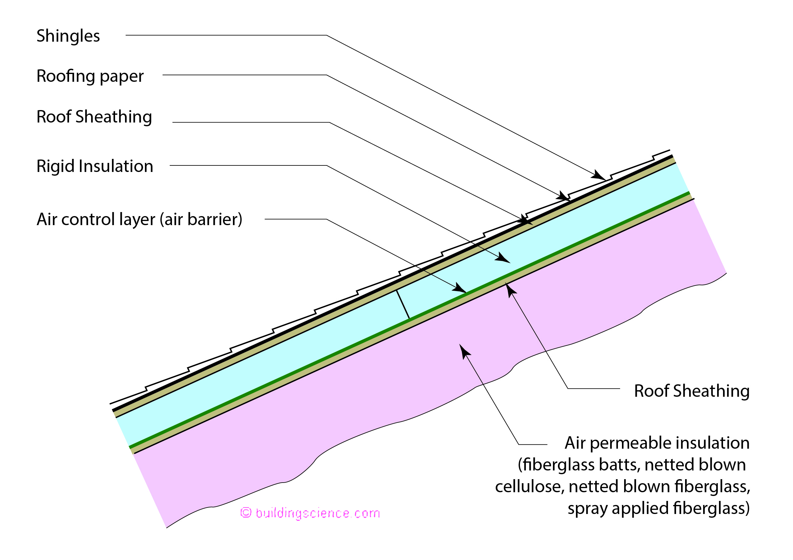
Figure 4: Insulation Above and Below Roof Deck - The rigid insulation can be “anything” above the roof deck. The main stipulation is the thermal resistance of this rigid insulation above the roof deck is based on Table 1. The “air permeable insulation” can be pretty much anything as well…just as long as the thermal resistance of this layer does not violate the “ratio”.
We assume a residential occupancy – a moisture load of approximately 35 percent relative humidity at 68 degrees F. Why this number? Because it gives us the right answer[5]…keep reading.
The performance requirement is quite specific – keep the temperature of the roof sheathing above 45 degrees F (7 degrees C)[6]. For calculation purposes an interior air temperature of 68 degrees F (20 degrees C) is assumed and the exterior air temperature is assumed to be the monthly average outside temperature of the three coldest months. Again, why this? Because it gives us the right answer….
This performance requirement is a “simplified” “conservative” approximation of all the historical experience and field work. Think of it as what it is…an “engineering coefficient”…..ok, more of an engineering equation providing boundary conditions….not derived from first principles but derived from observed experimentation and field experience.
This is clearly an insulation ratio – the R-value on the top of the roof sheathing compared to the R-value on the underside of the roof sheathing…and the ratio changes based on climate severity. The model codes specify the ratios based on climate zone (Table 1). Note how the ratio changes from approximately 10 percent to 70 percent as the assembly moves from hot climates to cold climates…
In Figure 4 the rigid insulation can be “anything” as in Figure 1. The main stipulation is the thermal resistance of this rigid insulation based on Table 1. The “air permeable insulation” can be pretty much anything as well…just as long as the thermal resistance of this layer does not violate the “ratio”.
Figure 5 is a variation of Figure 4. This one seems to confuse lots of folks. The rigid insulation on the top of the roof deck in Figure 4 is replaced with spray polyurethane foam on the underside of the roof deck. The thermal resistance of the spray polyurethane foam and the thermal resistance of the insulation under it must conform to the ratio stipulated in Table 1.
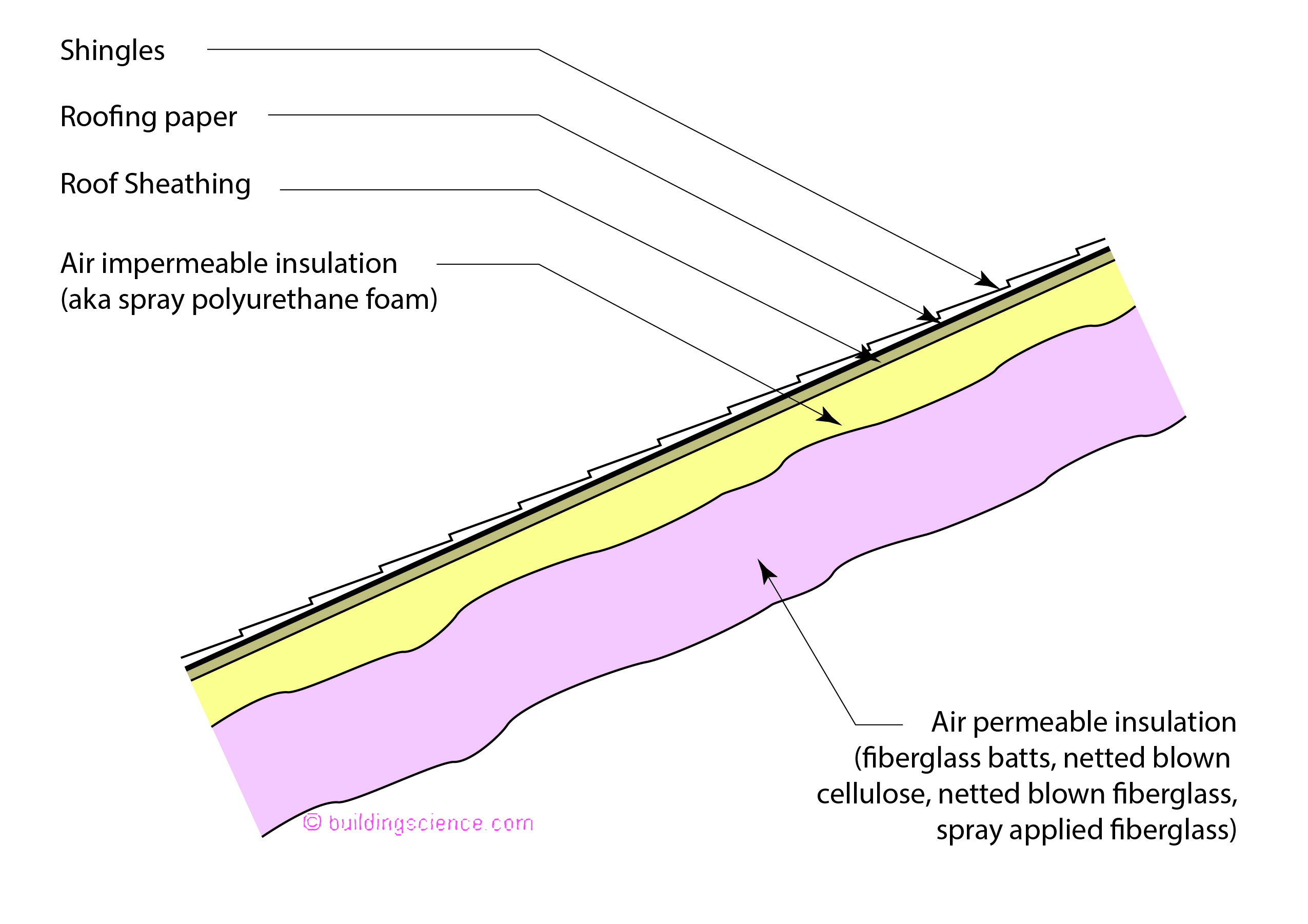
Figure 5: Variation - This one seems to confuse lots of folks. The rigid insulation on the top of the roof deck in Figure 4 is replaced with spray polyurethane foam on the underside of the roof deck. The thermal resistance of the spray polyurethane foam and the thermal resistance of the insulation under it must conform to the ratio stipulated in Table 1.
One other not so minor detail….once we get into IECC Climate Zone 5 or higher the spray foam must be closed cell. Of course in “code world” this is not made easy for normal folks to understand…the code language states “in Climate Zones 5, 6, 7 and 8 any air-impermeable insulation shall be a Class II vapor retarder”…. Yup, only closed cell foam meets this requirement[7].
Figure 6 is a variation of Figure 5. This assembly is a combination of closed cell spray foam and open cell spray foam. The thermal resistance of the two layers need to conform to the ratio stipulated in Table 1.
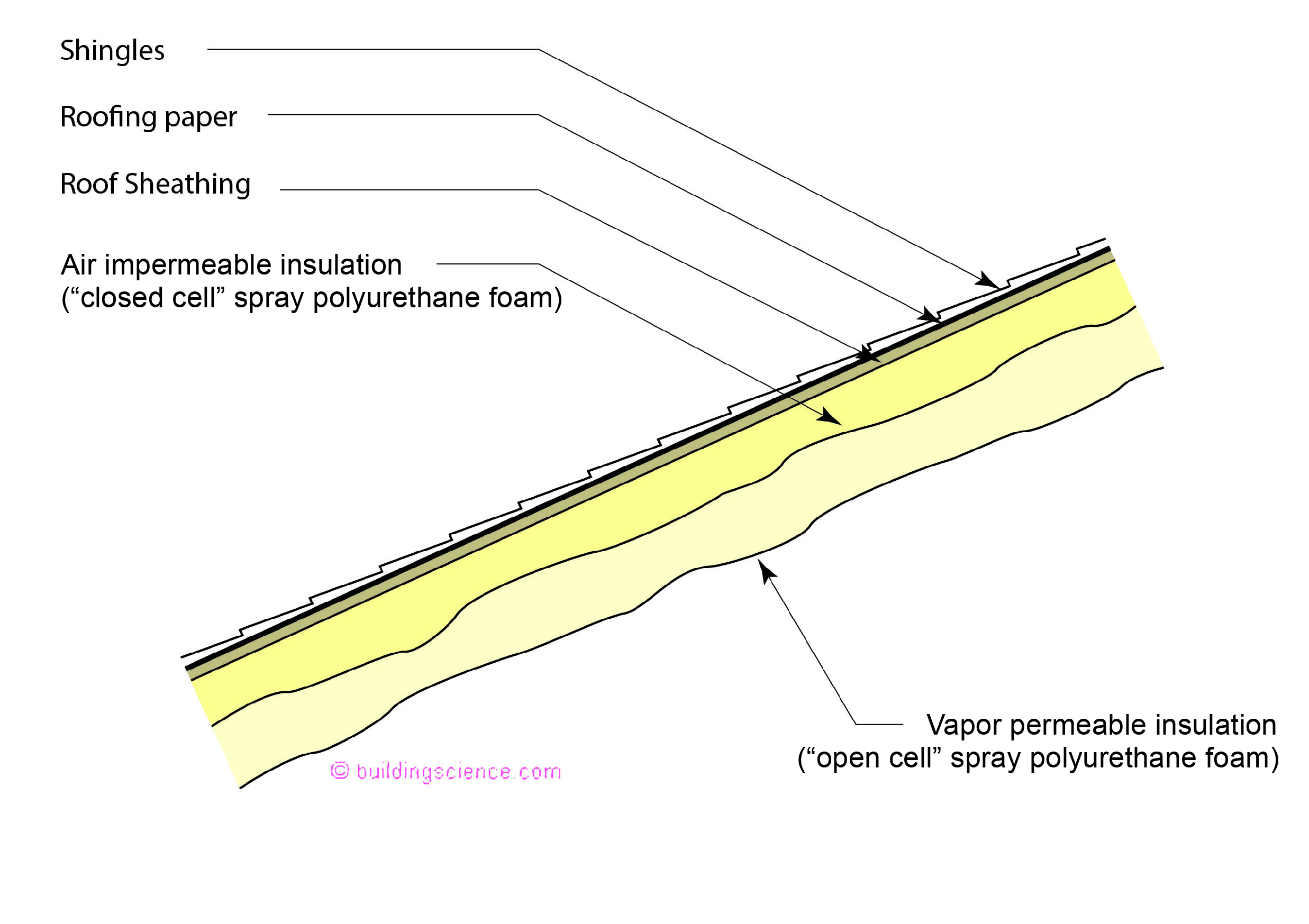
Figure 6: More Variation - This assembly is a combination of closed cell spray foam and open cell spray foam. The thermal resistance of the two layers need to conform to the ratio stipulated in Table 1.
As amazing as it seems all of the roof assemblies described in Figures 1 through 6 are explicitly allowed under the prescriptive language of the model codes…it is just not easy to decipher “code speak” into “construction speak”.
Let’s take a run at walls. Check out Figure 7. Nothing unusual there….right? Actually, there is. There is no interior vapor barrier[8]. This is explicitly allowed in the model codes if the temperature of the exterior sheathing is raised sufficiently to control condensation and moisture accumulation. Sound familiar? Figure 7 is the wall version of Figure 4. The key is the ratio of the thermal resistance of the rigid board insulation to the cavity insulation. Sound familiar? The ratio changes based on climate severity. The model codes specify the ratios based on climate zone (Table 2). Note how the ratio changes from approximately 15 percent to 50 percent as the assembly moves from marine climates to cold climates…
If you compare the ratios in Table 1 and Table 2 to each other you will note that the roof ratios are more conservative than the wall ratios. This is deliberate and due to two reasons. Roofs are not typically able to dry outwards as they almost always have a vapor barrier on the outside and walls are internally lined with gypsum board that is painted whereas roof assemblies rarely are. There is less outward vapor drive out of a roof than a wall and there is more resistance to vapor flow into a wall from the inside than in an attic.
Now check out Figure 8 and Photograph 1. Yup, Figure 8 is the wall version of Figure 5. The ratio of the closed cell spray polyurethane insulation to the cavity insulation must conform to Table 2. Let’s go to “code world”. The word “closed cell” spray polyurethane foam is not used….the actual language is “spray foam with a maximum permeance of 1.5 perms at the installed thickness”. Pretty much “closed cell” in “construction speak”.
So where are we with all of this? “Code world” is not usually “construction speak”. There are reasons for this…as we pointed out earlier. But “code world” does give us a great deal of flexibility if we appreciate its nuances. Hybrid attics and hybrid walls using a plethora of materials are examples of this flexibility if we take the time to “translate”.
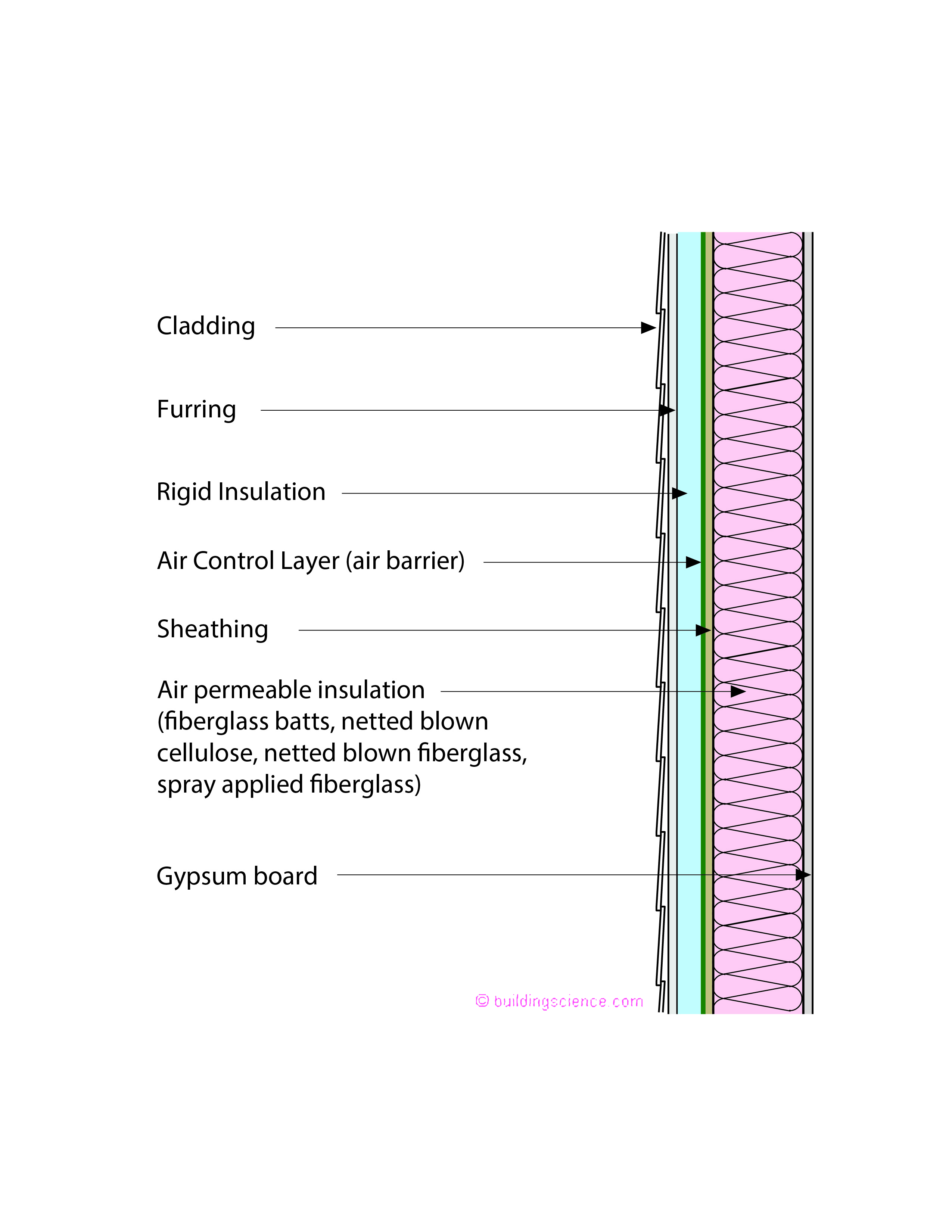
Figure 7: Wall Assembly - Nothing unusual there….right? Actually, there is. There is no interior vapor barrier. This is explicitly allowed in the model codes if the temperature of the exterior sheathing is raised sufficiently to control condensation and moisture accumulation. Sound familiar? Figure 7 is the wall version of Figure 4. The key is the ratio of the thermal resistance of the rigid board insulation to the cavity insulation.
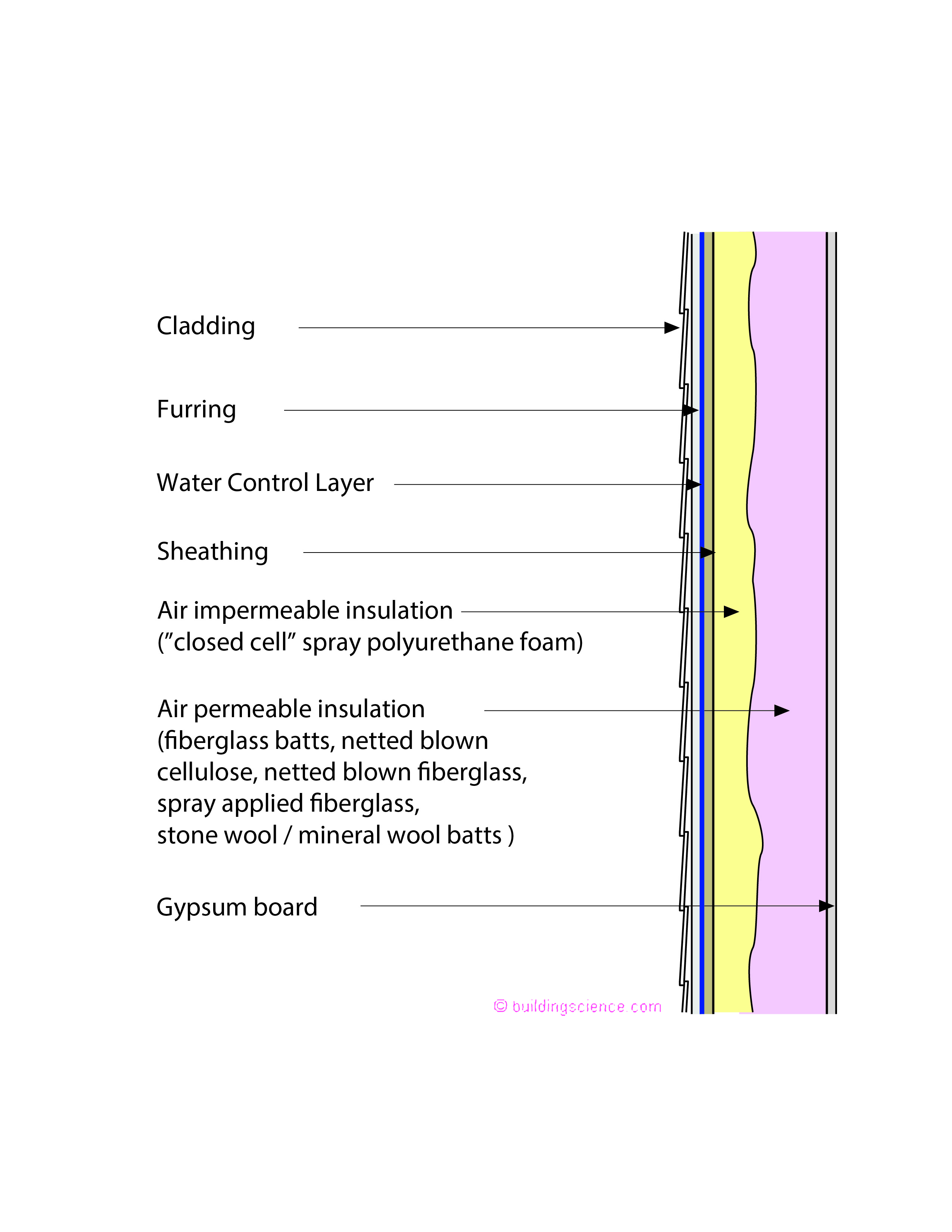
Figure 8: Hybrid Wall Assembly - Yup, Figure 8 is the wall version of Figure 5. The ratio of the closed cell spray polyurethane insulation to the cavity insulation must conform to Table 2. Let’s go to “code world”. The word “closed cell” spray polyurethane foam is not used….the actual language is “spray foam with a maximum permeance of 1.5 perms at the installed thickness”. Pretty much “closed cell” in “construction speak”.
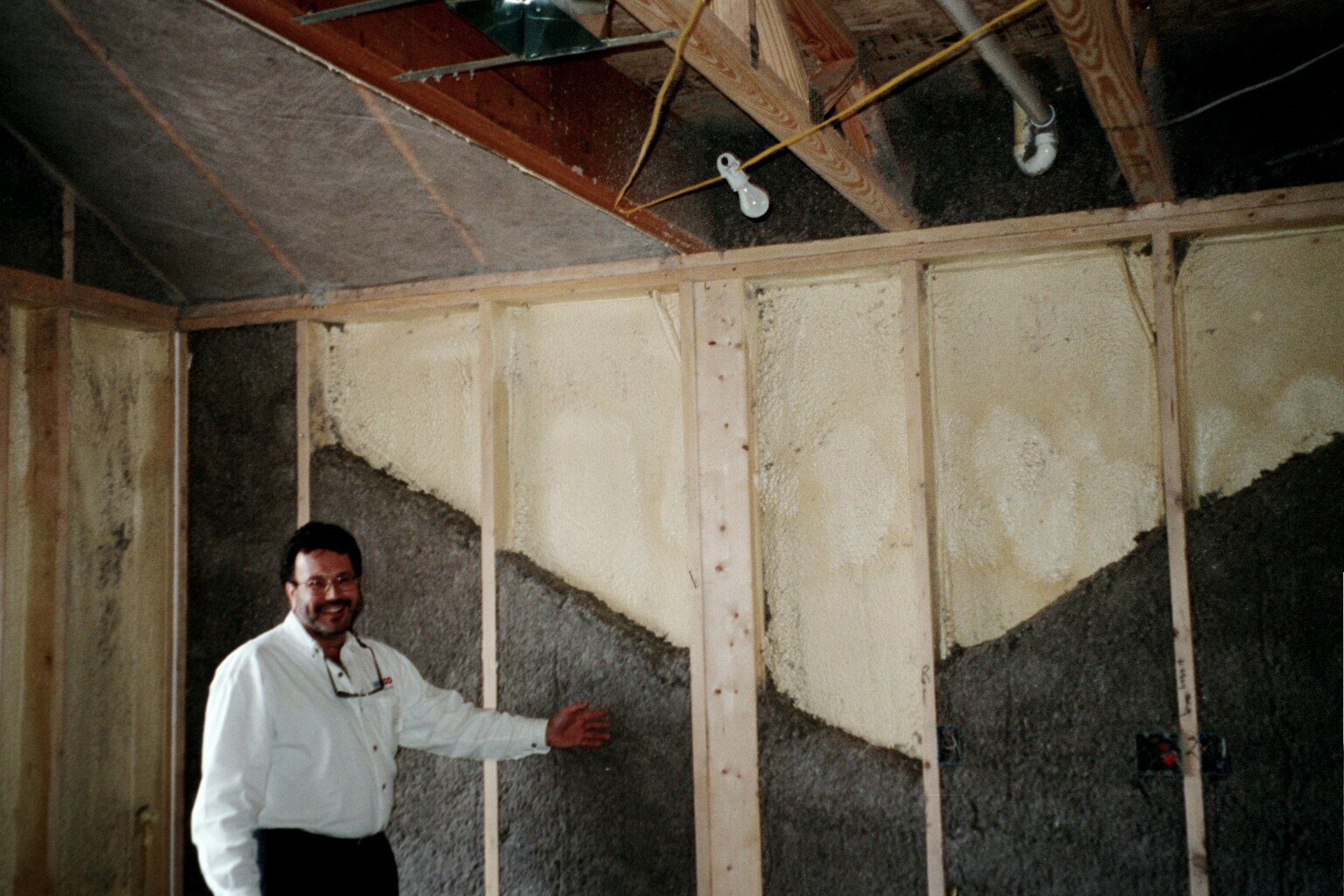
Photograph 1: Hybrid Wall Assembly Legend – Jay Epstein proudly presenting his hybrid closed cell spray polyurethane and damp spray cellulose wall before it became “fashionable”….Not going to give you the date of this photograph…but the hair color is not that dark anymore….
Insulation for Condensation Control*
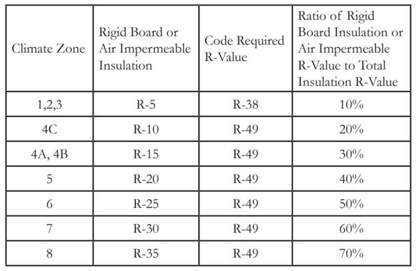
*Adapted from Table R 806.5 2018 International Residential Code
Insulation for Condensation Control*
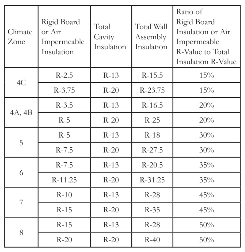
*Adapted from Table R 702.7.1 2018 International Residential Code
[1] Sir Winston Churchill – “It has been said that democracy is the worst form of government except for all the others…”
[2] Not strictly true…there are products that have properties in between the two…the “in-between-land” stuff…around 1 lb/ft3 density…they are not quite one or the other…we will leave them out of this discussion for the moment and get back to them some other day…
[3] For those of you that read footnotes this number should be familiar. It is the definition of an air barrier material and it comes from the leakage of drywall in the early 1980’s from “yours truly” as a result of Gus Handegord telling me to pick drywall as the basis for air barrier materials. Turns out that spray polyurethane foam (both types) meet this requirement.
[4] For the coldest parts of the winter…note that the roof sheathing moisture content drops quite quickly in the spring. The roof sheathing moisture content should be below 16 percent for the summer and fall. Where did this value come from? Historical experience, test house and test hut experimentation over several decades. These moisture content limits have been shown to also address mold growth…again…wait for it…based on historical experience.
[5] Yes, I know that interior moisture loads often go above 35 percent…but not 24-7…for months at a time…except in special use occupancies such as hospitals, art galleries, museums and natatoriums…or folks who deliberately over humidify or have no ventilation…can’t save everyone from being stupid…not our job…
[6] This is an average value over a three-month period…again based on historical experience, test house and test hut experimentation over several decades. Most of the work can be found in the DOE Building America sponsored research. The stuff we did (our team at Building Science Corporation) can be found on our website. Lots of papers…too many to list…if you are a building science geek…enjoy… Another way of looking at it is if you take 68 degree F air at 35 percent relative humidity and drop the temperature to 45 degrees F (the interior surface of the roof sheathing) you get 80 percent relative humidity and 80 percent relative humidity yields a water activity (wa) of 0.8 at the roof sheathing surface which is a reasonable mold limitation threshold…that also translates to 16 percent moisture content by weight…see previous footnote…and note that when it is cold not much bad stuff happens…back when we figured this out we did not have Hannu Viitanen to guide us….
[7] The code also states that you could apply a coating over the air impermeable insulation to create this Class II vapor retarder. Having pointed that out…I know of no practical coating that is relatively easy to apply that accomplishes this…
[8] Why would we want a wall without an interior vapor barrier? Ah, grasshopper…so that it can dry inwards. If you have a vapor barrier on the outside of the assembly it would be nice not to have one on the inside as well….