The owners of this circa 1800 Victorian have been postponing renovation and performance upgrade for years in anticipation of a major change in the household structure. With the likelihood of an aging parent’s arrival, they decided to rebuild a portion of the home and add new space to provide a ground floor bedroom with an unfinished office space above. Financial and technical support offered through National Grid’s Deep Energy Retrofit Pilot Program allowed the owners to incorporate a deep energy retrofit (DER) of the existing portions of the building into the larger project. Building Science Corporation provided technical support to the project on behalf of National Grid. The DER was implemented while the home was occupied.
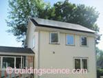
The overall performance improvement strategies for the existing structure include super-insulation enclosure upgrades; new heating, cooling, ventilation and water heating systems; and replacement of lighting and appliances with energy efficient products. The newly constructed addition supports a 5 kW photovoltaic array on the roof.
The owners have also decided to pursue the Thousand Home Challenge (THC). With the high performance enclosure and mechanical system, the on-site renewable technology as well as their low energy lifestyle, they are very promising candidates for the program.
Project Team: Kent Hicks Construction, Builder; Coldham&Hartman Architects, Architect and DER Lead; Building Science Corporation, Consultants and Technical Support; National Grid, Massachusetts, DER Pilot Program Administrator/Sponsors
Location: Northampton, Massachusetts
Description: 2,747 ft2, 3 bedroom, 2 bathroom, 2 stories with a full basement single family Victorian
Completion Date: August 2011
Design
To support the project’s low-energy goals, the enclosure retrofit is designed to provide super insulation and aggressive airtightness. Because the project team considers building durability and indoor air quality essential to high performance building, the retrofit design provides robust water management systems.
The architect selected a super insulation approach for the roof and wall that supplements fibrous cavity insulation with a thick layer of insulating sheathing to the exterior of existing sheathing. The approach is compatible with assemblies that have restricted access to framing cavities such as with cathedralized ceilings or to situations where space for insulation between and below rafter framing is otherwise limited. Adding a thick layer of insulation exterior to the sheathing also provides robust condensation risk management.
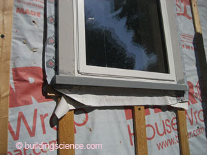
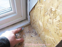
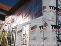
The design employed a layer of sheathing added over existing sheathing as the primary airflow control layer. A layer of plywood is used at the roof. The walls use a proprietary sheathing system consisting of specialized tape and OSB with a water and air control coating. This sheathing system is also used to provide extensions at window openings.
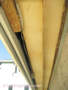
The design uses the “chain saw” approach at the roof-wall interface. In this approach, roof overhangs are sawn off at the wall sheathing so that the air control layer and thermal control layers of the roof connect directly to the corresponding control layers of the wall system.
The design includes multiple water control layers in the roof and wall assemblies. On top of the supplemental sheathing, the design uses two layers of foil-faced rigid board insulation with seams offset and taped. For the walls, the primary water control layer is a shingle-lapped layer of housewrap installed over the face of the rigid insulation. Wood furring creates a drainage and ventilation space between the fiber-cement cladding and the housewrap. On the roof, asphalt shingles and underlayment are installed over a proprietary air/water control sheathing system (as for walls) that is installed over the insulating sheathing.
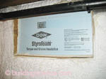
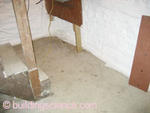
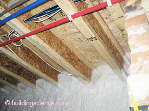
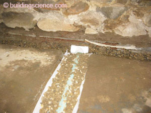
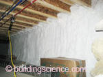
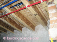
Water issues in the basement are managed by gravel trenches cut into the existing slab and an interior perimeter drain connected to sumps. Closed-cell spray foam on the brick-and-rubble-stone walls and rigid foam surrounding the newly cast slab provide insulation and also direct water to the sub-slab drainage system.
Enclosure Design
Roof Assembly: R-60 (nominal) Unvented roof assembly: Rafter bays netted and dense-packed with cellulose insulation, ½” plywood over existing board sheathing; fully adhered membrane; 4” polyisocyanurate insulating sheathing in 2 layers; taped OSB sheathing system (Zip System® Roof); 2nd layer of fully adhered membrane; asphalt shingles.
Wall Assembly: R-39 (nominal): Dense-packed cellulose insulation in existing wall framing cavities; taped OSB sheathing system (Zip System® Wall) over existing board sheathing; two layers of 2” foil-faced polyisocyanurate insulating sheathing; housewrap; ¾” furring strips; fiber cement siding.
Window Specifications: Serious Windows triple-glazed, krypton gas, low-E fiberglass windows; U=0.14-0.17, SHGC=0.33-0.42; windows installed over strapping at exterior face of insulating sheathing; rigid insulation inserts at basement windows.
Air Sealing: Taped OSB sheathing system, walls and window extension boxes; adhered membrane over 1/2” plywood at roof; “Chain saw” retrofit approach at roof-wall transition; open-cell spray foam at sill beam with closed-cell spray foam extending down and over the newly cast concrete slab.
Foundation Assembly: Conditioned basement with 5” of closed-cell spray foam at existing fieldstone and brick foundation walls; open-cell spray foam at sill beam; intumescent coating on spray foam; new concrete slab cast in “bathtub” of 2” high-density EPS over existing slab, interior drain and gravel.
Construction
Maintaining the operation and use of the home during the retrofit provided interesting sequencing issues. The specialized sheathing system installed over the existing sheathing as an air flow control measure also provided robust temporary weather protection through a New England winter while the project waited for warmer weather to permit window replacement and exterior insulation. Demolition in the basement was also held in abeyance through the winter, as the existing heating and water heating equipment were located in this space.
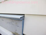
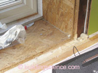
The builder brought a passion for perfection that was evident in implementation of water management and air sealing details. No effort (or canned foam) was spared in ensuring a thorough air seal between the framed wall system and the foundation wall. A beveled cap over window head casing trim is an example of the attention to water management details. This small trim piece makes it virtually impossible for the metal cap flashing to have a back slope. The builder opted to apply two layers of adhered ice and water membrane at the roof: one over the plywood sheathing beneath exterior insulation and one to the sheathing installed over the insulation.
Mechanical Design
Heating and Cooling: ClimateMaster ground-source heat pump system*; Carrier air handler unit located in the conditioned basement.
Ventilation: Venmar EKO 1.5 Energy Recovery Ventilator (ERV) located in the conditioned basement and ducted to central distribution system.
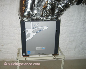
Energy recovery ventilator (ERV)
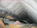
Space Conditioning Distribution: Heating, cooling and ventilation ductwork located entirely within the conditioned space.

Space Conditioning Distribution
DHW: GE GeoSpring Hybrid Water Heater* located in the conditioned basement.
Lighting: Combination of CFL and LED lighting.
Appliances: ENERGY STAR® appliances.
* The client elected to pursue all-electric heating and water heating system. This was not the recommendation of the architect or BSC.
Testing and On-Site Technical Support
Through both on-site and remote technical support, BSC was able to help the project identify feasible improvements and simplifications. Closed-cell spray foam was substituted for the open-cell at the sill in order to provide a drying mechanism for the framing. BSC eased the architect and builder into eliminating a planned drainage mat over the existing slab and at the new slab perimeter by demonstrating how rigid foam insulation against the rubble stone created a path to the drainage system. Despite generally excellent implementation of water management details, BSC was able to point out a few instances of missing flashing at critical locations.
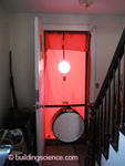
BSC performed a post-retrofit, single-zone air leakage test for the entire home. A guarded air leakage test was then used to obtain data to apportion the measured leakage between the new construction (addition/rebuild) and retrofit portions of the project. The older portion of the building measured at 348 CFM @50 Pa (0.8 ACH 50 and 0.06 CFM per square foot of enclosure) and the new construction addition measured 125 CFM @50 Pa (0.9 ACH 50 and 0.06 CFM per square foot of enclosure).
Moving Forward
Encouraged by the achievements in this project, the builder plans to pursue aggressive air tightness on subsequent projects. He has also developed an appreciation for installation of windows in plane with the primary water control layer.
Subsequent to this project, the architect has ushered several projects into the National Grid Deep Energy Retrofit Pilot program.
Monthly gas and electric bills will be collected from the homeowners to compare them to the previous energy use.
Design Challenge: Exceptional Airtightness The post-retrofit air leakage results were very impressive. The architect and builder put a lot of effort into tightening up the existing portion of the home as well as the new construction addition. The sheathing system employed for airflow control provides a robust and durable substrate for air sealing connections to other assemblies and penetrations through the assembly. The “chain saw” approach at the roof-wall transition also greatly simplifies implementation of robust airflow control. A fully adhered membrane wrapped from the airflow control sheathing at the roof onto the airflow control sheathing of the wall. Two layers of 2” foil-faced polyisocyanurate insulating sheathing were added to the walls and roof with seams offset and sealed with sheathing tape. Well-applied spray foam insulation and a new concrete slab provided robust airflow control at the foundation level. The spray foam also facilitates robust air barrier transitions to the slab and framed wall. |


