The owners of this single family home initially set out to remodel the basement into conditioned space and upgrade the heating and water heating systems. Working with a builder oriented toward high performance construction, the owners decided to expand the project and turn it into a Deep Energy Retrofit (DER) after the builder introduced them to the National Grid DER pilot program.
Original project scope already included thick interior insulation for the foundation walls, a new insulated basement slab, new boiler and water heater. The expanded comprehensive DER scope included exterior and interior insulation and recladding of the walls and roof, new triple- and double-glazed windows, replacement of the central air conditioning system with a high efficiency air-source heat pump, and provision of a Heat Recovery Ventilator (HRV) for mechanical ventilation.
This test home provides an example of a thoroughly comprehensive retrofit that did not involve major additions or changes to the building footprint but, nonetheless expanded living space by including the basement within the thermal enclosure.
The retrofit was also implemented while the home was occupied. The renovation took 10 months to complete and the house was completely turned back over to the homeowners in June of 2011.
Project Team: Vahe Ohannessian, Architect, Builder and DER Lead; Building Science Corporation, Consultants and DER Technical Support; National Grid, Massachusetts, DER Pilot Program Administrator/Sponsor
Location: Newton, Massachusetts
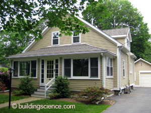
Description: 2,044 ft2 (including conditioned basement), three bedroom, two bathroom, 11/2 stories plus full basement, single family Cape
Completion Date: June 2011
Estimated Annual Energy Savings: Projected 31% energy use reduction compared to pre-retrofit conditions
Design
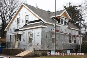
Retrofit of exterior walls by applying thick layers of insulating sheathing can be pursued without necessary disruption to the interior. The homeowners, who occupied the home throughout the project, decided to take upon this approach. Cavity insulation was installed or supplemented where missing or inadequate.
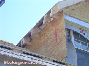
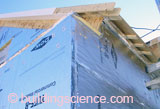
A significant design direction pursued by this project is the “chain saw” retrofit approach to the roof-wall transition of the main roof. In this approach, the eave and rake overhangs of the roof are removed to allow the air and thermal control layers of the roof to connect directly to the corresponding control layers of the wall system. The “chain saw” approach allows for a simple transition of airflow control and also eliminates thermal bridging of roof framing at eaves and rake transitions. This approach is compatible with re-roofing and reconstruction of roof overhangs such as is often recommended with wall retrofit in order to provide adequate overhang. The necessary reconstruction of overhangs also provides an opportunity to address aesthetic goals and to increase protection of walls.
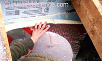
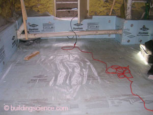
In order to allow a lower slab, the design involved excavation of the existing basement floor and installation of a concrete underpinning wall beneath the existing rubble stone foundation wall. The design demonstrates a connection of foundation wall water control to the sub-slab drainage system. Polyethylene sheet vapor retarder placed between rigid insulation and the new concrete slab continues up the face of the underpinning wall to the base of the rubble stone wall. The polyethylene is embedded in the closed-cell SPF applied to the foundation wall. Should liquid water pass through the foundation wall, it would be directed by the closed cell insulation and then by the polyethylene sheet to the sub slab drainage. Irregularities in the surface of the concrete provide drainage pathways for liquid water to reach the sub-slab drainage system.
The wall assembly for this project establishes the exterior face of the insulating sheathing as the drainage plane while the housewrap serves as the primary air control layer. The multiple layers of materials in this system provide additional control. The thickness of exterior insulation also places the rain shedding layer further from water sensitive structure.
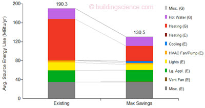
Modeled Source Energy Savings
(Image from BSC generated by NREL’s BEOpt 1.1 for retrofits)
Enclosure Design
Roof Assembly: R-56 (nominal) Unvented roof assembly with vented over-roof: rafter cavities at eave space filled with existing fiberglass batts encapsulated with open-cell spray foam, cellulose insulation at cathedral ceilings, open-cell spray foam above flat ceiling; housewrap over existing sheathing, two layers of 2” foil-faced polyisocyanurate insulating sheathing, 2x4 purlins, ½” plywood, underlayment and asphalt shingles.
Roof Assembly
Wall Assembly: R-39 (nominal): Existing 2x4 wall framing cavities with fiberglass insulation supplemented with dense-packed cellulose where needed, housewrap, two layers of 2” foil-faced polyisocyanurate insulating sheathing, ¾” furring strips, fiber cement siding.
Wall Assembly
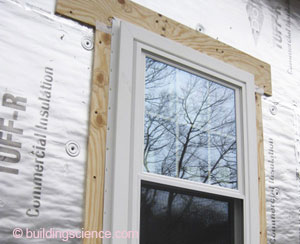
Window Specifications: New Harvey Tribute triple-glazed, argon gas, low-E vinyl windows, U=0.2, SHGC=0.21; six Harvey Majesty, double-glazed, argon, low-E wood windows, U=0.3, SHGC=0.24; windows installed proud of drainage plane on blocking.
Window Specifications
Air Sealing: “Chain saw” retrofit approach; housewrap, air control layer wraps directly from roof to wall; open-cell spray foam at framing sill, closed-cell over rubble stone foundation wall, taped rigid insulation at concrete underpinning wall; new concrete slab.

Air Sealing
Foundation Assembly: Conditioned basement with 3” closed-cell spray foam applied to rubble stone foundation wall in new 2x6 stud walls finished with drywall, 12” of open-cell spray foam extending up the mud sill, 2” XPS at interior of concrete underpinning wall; gravel drainage pad, 2” of XPS insulation and polyethylene vapor retarder beneath new concrete slab; radiant subfloor finished with hardwood flooring.
Foundation Assembly
Construction
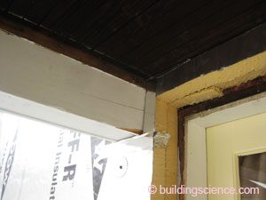
During the course of construction, the builder devised solutions for conditions of continuous exterior insulation. A strip of plywood was used at the top of the gables to support a rake overhang that was otherwise aligned with exterior insulation of the roof. The added thickness of the roof would have brought the roof surface too close to the sill of dormer windows. The insulation was thickened at the face of the dormer to align the face with the wall below and to allow the eave overhang to break at the dormer.
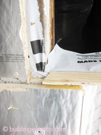
In other areas the application of exterior insulation presented challenges. Installation of exterior insulation over the housewrap, before making critical airflow control connections complicated many of the airsealing details (see Design Challenge). The builder purchased windows with an integral trim channel designed to receive lapped siding. Windows were installed to blocking on top of the exterior insulation in order to align the window’s receiving channel with the siding (which is installed over furring strips to create a ventilation/drainage space as well as for attachment). Installing the windows this way created significant challenges to the implementation of proper flashing and airflow control.
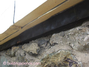
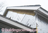
A common mistake with exterior insulating sheathing used as the drainage plane is to place step flashing at the plane of the existing sheathing rather than at the face of the insulating sheathing. In the photo on the left, the roof-wall flashing is not at the face of the drainage plane and the drip edge creates a condition where water may be directed in behind the drainage plane. This situation was corrected for this home.
Mechanical Design
Heating and Cooling: Condensing boiler located in the basement mechanical room for existing hot water baseboards and new Warmboard radiant heating in the basement; high efficiency air-source heat pump using expanded central A/C ductwork.
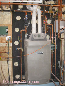
Condensing boiler
Ventilation: Bryant Energy Recovery Ventilator (ERV) ducted to central air handler located in the attic.
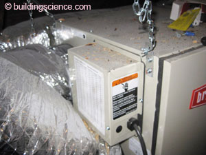

Energy recovery ventilator (ERV)
Space Conditioning Distribution: Ductwork entirely inside the conditioned space.
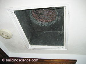
Return duct
DHW: SuperStor® Ultra storage hot water heater supplied by boiler located in the basement mechanical room.
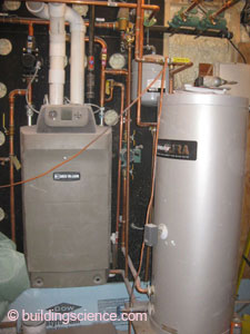
Boiler and hot water storage tank
Lighting: All CFLs in light fixtures.
Appliances: ENERGY STAR® appliances.
Testing and On-Site Technical Support
BSC conducted site visits to review construction details with the builder and to offer technical guidance. During one such visit, BSC guided the builder and his crew through a mock up window installation to ensure proper installation of flashings and connections of the air control layers. BSC also worked with the builder to develop a detail to protect the bottom of the insulating sheathing from the weather and rodents while still permitting the assembly to drain.
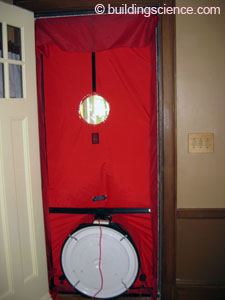
BSC performed a post-retrofit air leakage testing to assess the air leakage reduction relative to pre-retrofit conditions. The pre-retrofit air leakage measurement was 11.2 ACH50 and the post-retrofit measure was 4.9 ACH50.
Because the results were somewhat disappointing, BSC conducted an additional site visit to identify major sources of air leakage. With the house alternately depressurized and pressurized, BSC inspected the enclosure with a both a small handheld smoke generator and a larger theatrical smoke machine. While no significant problems were observed in the enclosure construction, BSC did find a problem with outside air dampers on the ERV that requires remediation.

Moving Forward
Monthly gas and electric bills will be collected from the homeowners to gauge performance of the retrofit strategies employed.
The builder plans to correct the set up of the ERV to ensure the dampers are powered properly and close when the ERV is not operating.
Design Challenge: Airtightness of the Enclosure Implementation sequence was a critical factor in air flow control. The housewrap – intended to be the primary airflow control – and exterior insulation had been installed prior to removing the existing windows. This made it difficult to transition the air flow control layer into the window opening and to provide connection to the new window. To make the connections, sections of insulating sheathing around the windows had to be removed to allow pieces of air control membrane (house wrap or adhered membrane) to attach to in-place housewrap. Also, the housewrap had not been sealed to the base of the wall prior to installation of exterior insulation leaving limited options for a robust connection there. While the builder pursued a “chain saw” approach at the roof-wall interface, porches were left attached thus precluding continuous air control and insulation layers at these locations. Sealing around the intervening framing and roof decks proved challenging.
|