Hanging cladding – hang on cladding, cladding hang on[1]..
Continuous exterior insulation is such an obvious thing to do….and we are finally getting serious about it…but we still seem to go out of our way to defeat its intent.
One of the arguments for the use of continuous exterior insulation is to address the thermal bridging at the structural components of building assemblies…especially steel stud/frame assemblies. Done correctly it is a big deal energy wise. It is pretty dumb to add continuous exterior insulation with the same type of thermal bridging that the continuous exterior insulation is intended to address.
It boggles the mind to use a Z-bar – cold formed metal – for cladding attachment over continuous exterior insulation. Not sure that they still teach this in public school….but metal is conductive not just for electricity but also for heat[2].
Figure 1 and Figure 2 are common details…apparently the exterior gypsum sheathing is supposed to be the “thermal break”. What is the point of using continuous exterior insulation when you reduce its effectiveness by 30 percent or more[3]?
Attaching cladding through continuous exterior insulation should be done in a manner that reduces thermal bridging. There are numerous approaches that are based on the weight of the cladding and the thickness of the continuous insulation.
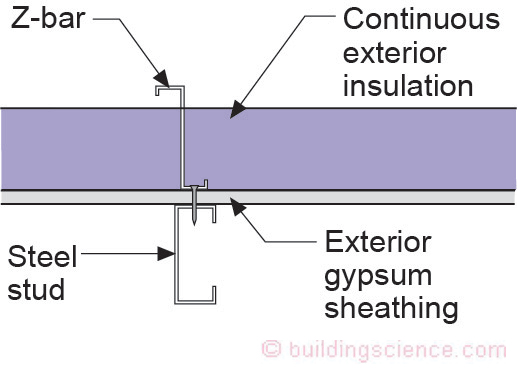
Figure 1: Cold Formed Metal Cladding Attachment—Apparently the exterior gypsum sheathing is supposed to be the “thermal break”. What is the point of using continuous exterior insulation when you reduce its effectiveness?
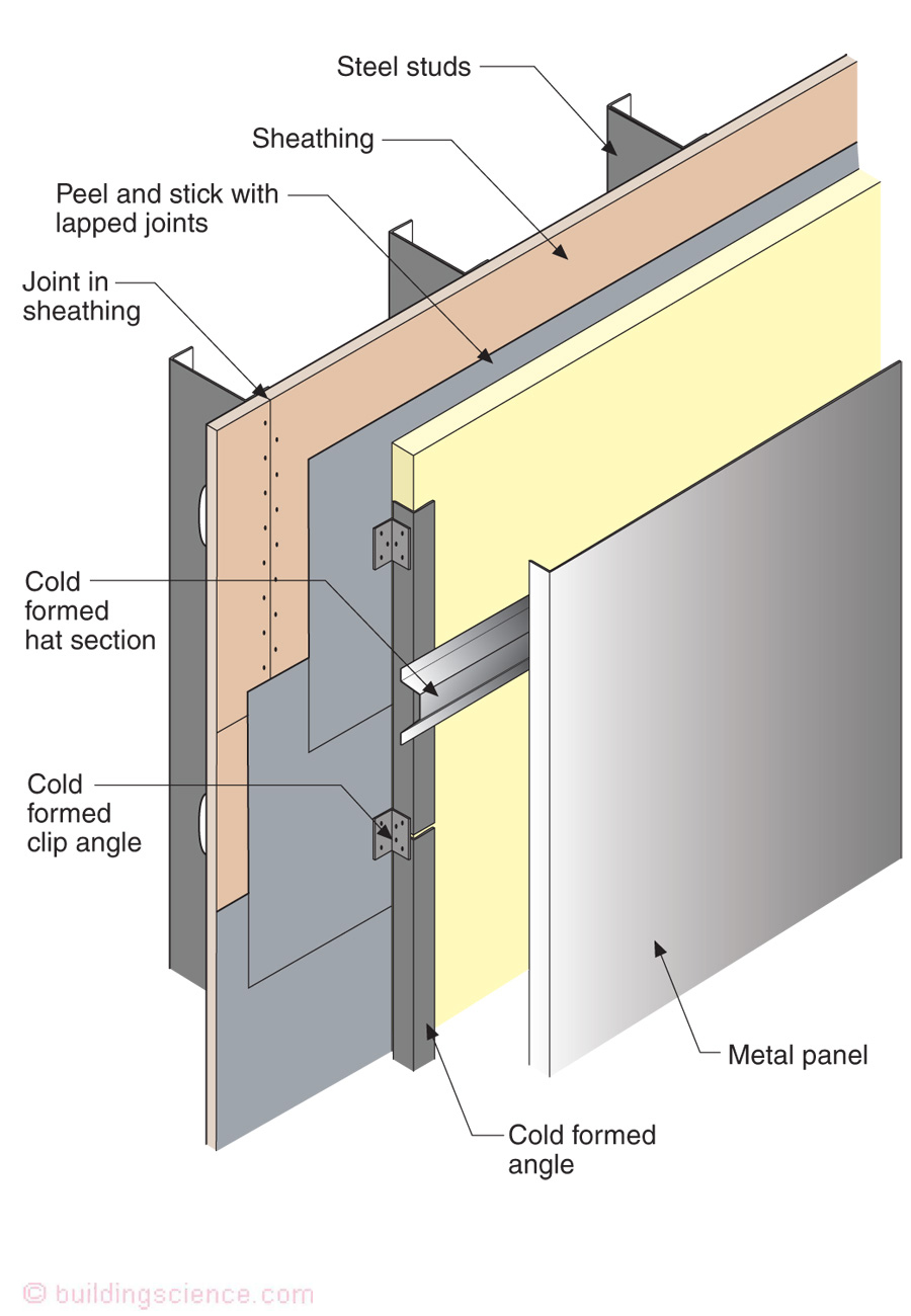
Figure 2: Cold Formed Metal Is Conductive—Metal is conductive not just for electricity but also for heat.
A simple way to address the issue is to off-set the cold formed metal from the exterior sheathing with clip angles (Figure 3). This is easy…but it drives structural engineers crazy….so…we have a compromise[4]…use of two layers of cold formed metal that are oriented perpendicular to each other to reduce thermal bridging (Figure 4). This approach is sometimes referred to as the “clip and rail” approach. Note that it requires two layers of continuous exterior insulation.
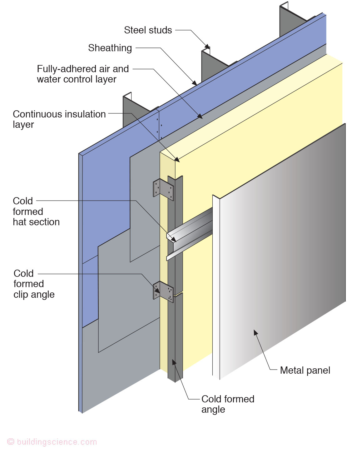
Figure 3: Clip Angles—A simple way to address the thermal bridging issue is to off-set the cold formed metal from the exterior sheathing with clip angles.
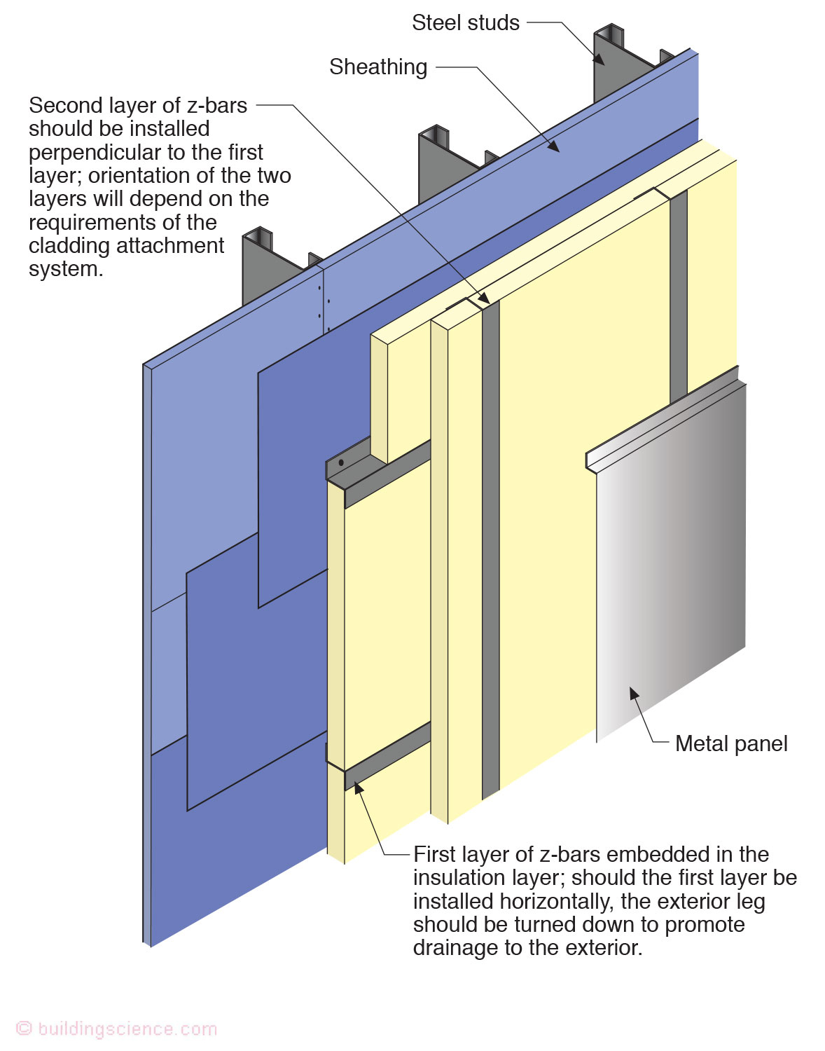
Figure 4: “Clip and Rail” Approach—Two layers of cold formed metal that are oriented perpendicular to each other to reduce thermal bridging. Note that it requires two layers of continuous exterior insulation.
A variation of the “clip and rail” approach is to use a non-thermally conductive fiberglass “clip” (Photograph 1). That is pretty impressive.
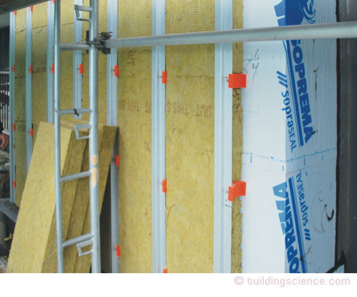
Photograph 1: Non-Thermally Conductive Fiberglass “Clip”
It gets better… Hat channels can be used with long screws to provide cladding attachment (Figure 5 and Figure 6).
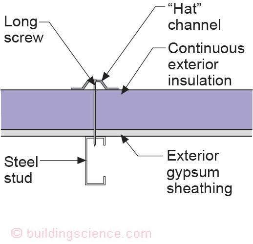
Figure 5: Hat Channels—Hat channels can be used with long screws to provide cladding attachment. Not much conductivity with only the screw passing through the exterior continuous insulation.
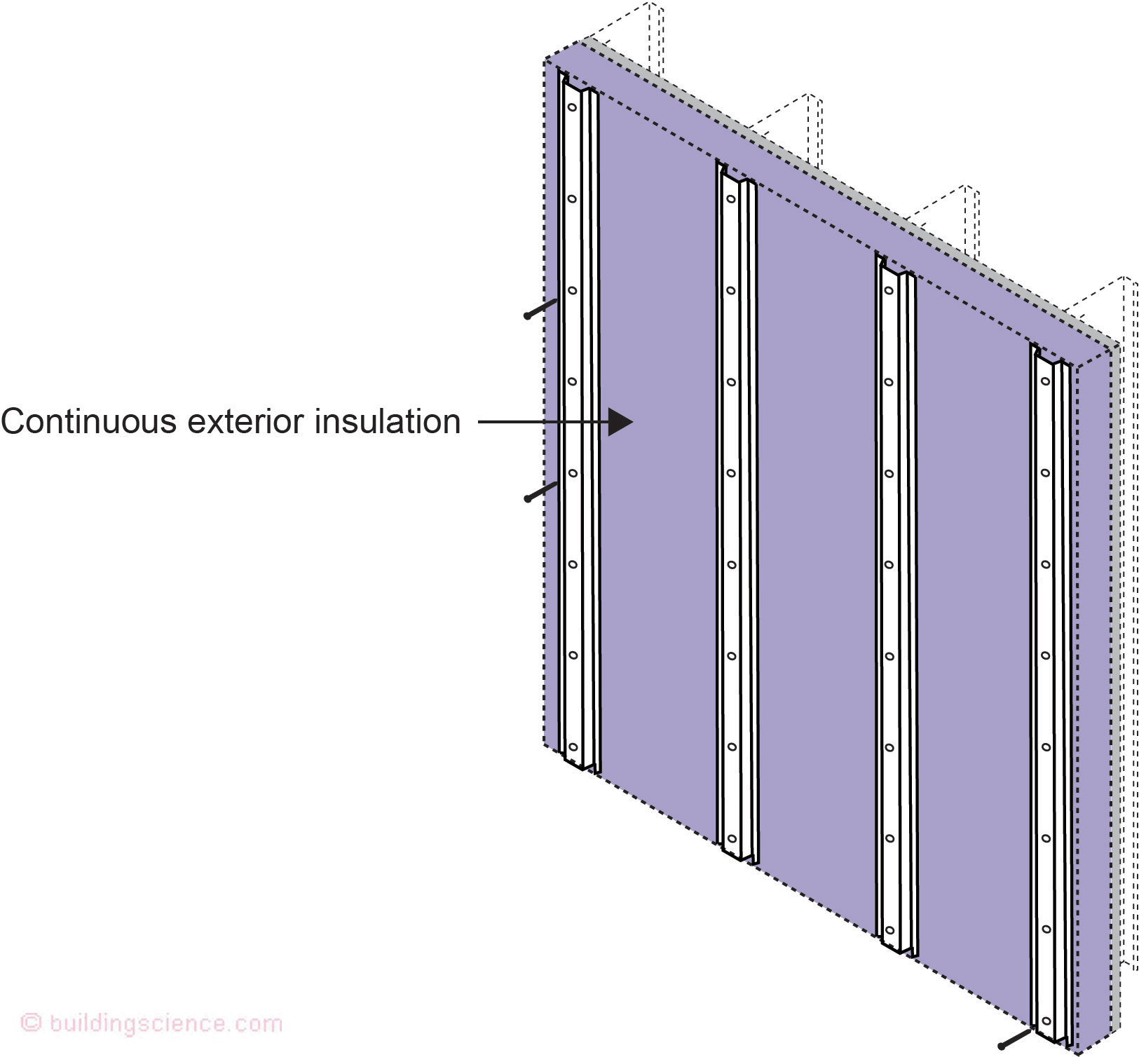
Figure 6: More Hat Channels—Long screws used as a thermal break.
Not much conductivity with only the screw passing through the exterior continuous insulation. Adding horizontal girts increases rigidity and provides increased flexibility for cladding types (Figure 7). The use of hat channels and long screws depends on the compressive strength of the continuous insulation and weight of the cladding and is typically calculated using a truss analogy (Figure 8 and Figure 9). The model codes now provide guidance on screw spacing and cladding weights.
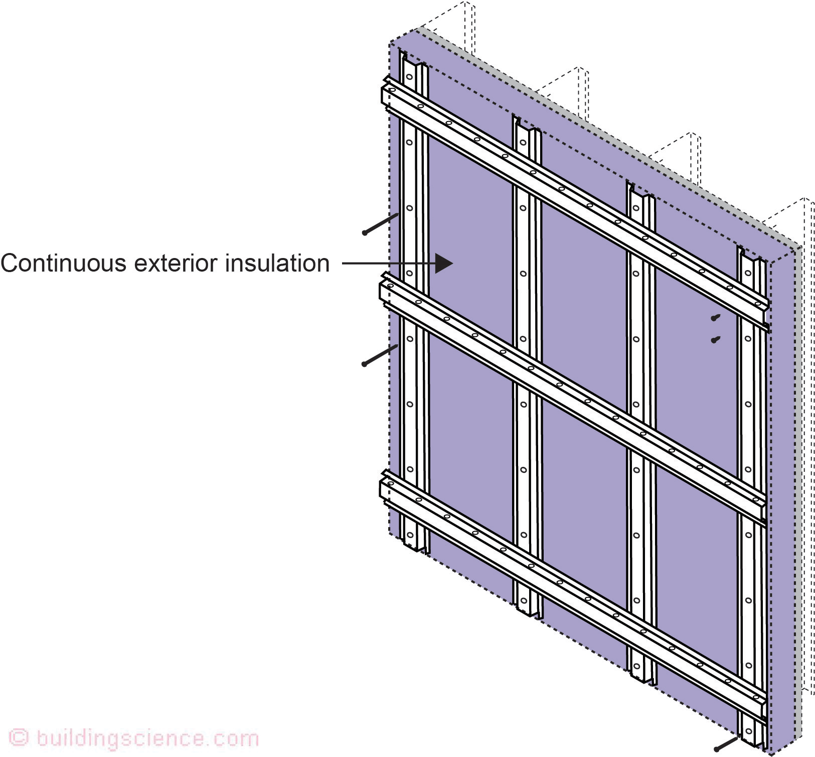
Figure 7: Horizontal Girts—Adding horizontal girts increases rigidity and provides increased flexibility for cladding types.
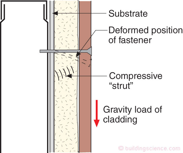
Figure 8: Hat Channel Geometry—The geometry of the hat channel and the screw depends on the compressive strength of the continuous insulation and weight of the cladding.
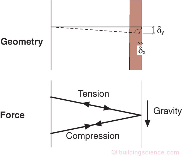
Figure 9: Truss Analogy—The model codes guidance on screw spacing and cladding weights is typically calculated using a truss analogy.
How about that…using long screws help us from screwing up exterior continuous insulation….
That was easy…are we done? Nope, now comes the real hard part.
Thermal Bridging at Relieving Angles and Lintels
Brick veneer construction that typically relies on relieving angles and lintels for structural support often has the most significant thermal bridging issues. Yes, yes we were here before (“BSI-062: Thermal Bridge Redux”, June 2015), but we need to remind everyone again because we aren’t dealing with it in any major way yet.
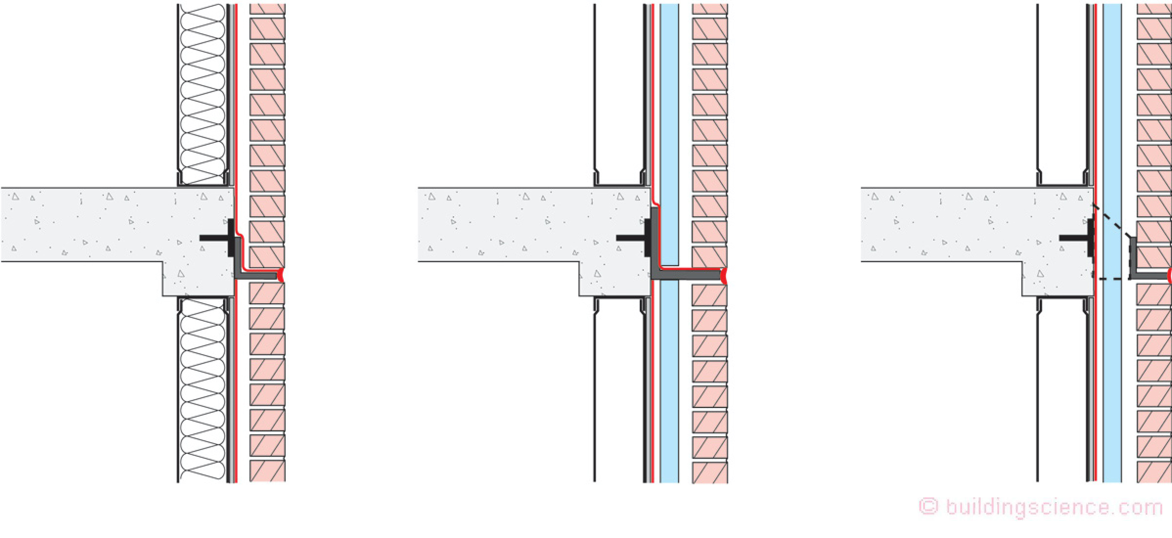
Figure 10: Relieving Angle Thermal Bridging—Typical steel stud construction on a concrete frame with relieving angles welded to slab edges are huge thermal bridges. Such relieving angles often go completely around the building. Adding continuous insulation reduces the thermal bridging of the steel studs but does not address the thermal bridging of the relieving angle.
Figure 10 shows three typical approaches to brick veneer construction ranging from significant thermal bridging to little thermal bridging. Typical steel stud construction on a concrete frame with relieving angles welded to slab edges are huge thermal bridges. Such relieving angles often go completely around the building. Adding continuous insulation reduces the thermal bridging of the steel studs but does not address the thermal bridging of the relieving angle.
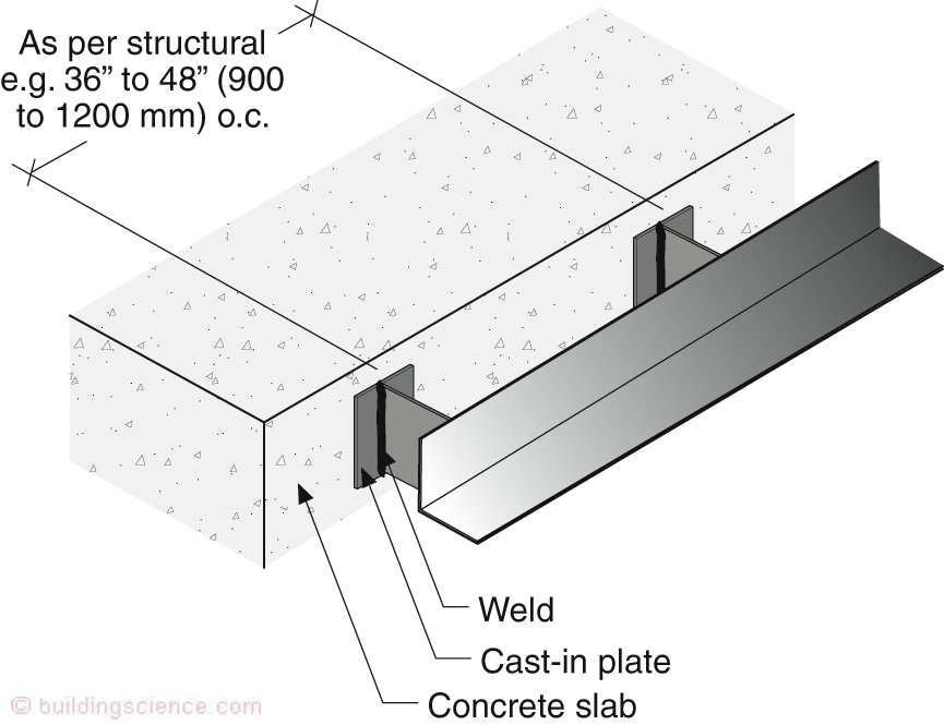
Figure 11: Relieving Angle “Stand-Off”—The best way to deal with relieving angles is to hang them off of the building with a “stand-off” and then spread them out every second or third floor. The stand-off’s can be welded to plates cast into slabs or welded to structural steel supports.
The best way to deal with relieving angles is to hang them off of the building with a “stand-off” (Figure 11) and then spread them out every second or third floor. The stand-off’s can be welded to plates cast into slabs or welded to structural steel supports. This allows insulation to run past the relieving angle in a continuous manner (Figure 12).
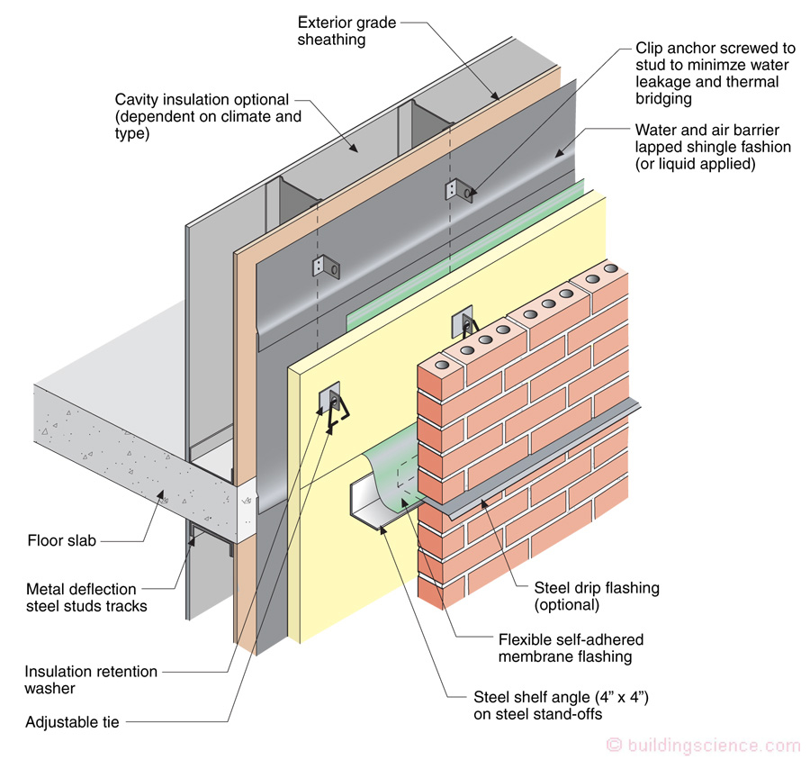
Figure 12: Continuous Exterior Insulation—The “stand-off” allows insulation to run past the relieving angle in a continuous manner.
Similarly, lintels supporting brick over punched openings should be held away from the structural “back-up’ wall assembly allowing the insulation to be continuous (Figure 13).
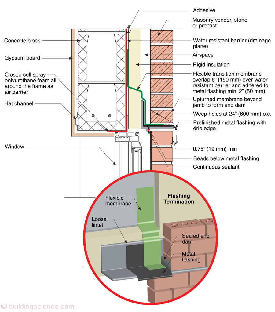
Figure 13: Controlling Lintel Thermal Bridging—Lintels supporting brick over punched openings should be held away from the structural “back-up’ wall assembly with “stand-offs” allowing the insulation to be continuous.
Time to get serious about this thermal thing…the heat is on…don’t want to get “Frey’d”[5].
Footnotes
[1] Pretty sure this was a song from the McCoys…sometime in 1965….or I might be confusing cladding with sloopy…
[2] This often seems to be left out of the structural engineering curriculum.
[3] Lots and lots of work done over the years…I use 30 percent but it can be much higher…start with ASHRAE Fundamentals….
[4] At the end of the day always, always go with the structural engineer…when I make a mistake people can get wet…boo who…when a structural engineer makes a mistake people can die…
[5] Glen Frey, “The Heat Is On” sang this for the film Beverly Hills Cop (1984). Note that the Toronto Maple Leafs finished last in the entire NHL that year….