…. at Fulton and his steamboat
Hershey and his chocolate bar….
OK, this is one of my all-time favorite songs. George and Ira Gershwin. Performed for the first time by Ginger Rogers. But everyone sang it…Bing Crosby, Frank Sinatra, Tony Bennett. Even Lady Gaga. But the all-time best was Ella and Louis. Yes, Ella Fitzgerald and Louis Armstrong. So where am I going with this? Hang on for the connections.
Robert Fulton, an engineer of course, developed a steamboat that actually worked ferrying passengers between New York City and Albany around 1800. Yes, I know, the English and the French[1] got there first, but Fulton actually made it work.[2] Steamboats, what a fabulous way to go. Distinctive sound. Anyway, a bunch of French dudes (aka “trappers”) in the late 1820’s traveling along the Yampa River in what is now Colorado heard a “chug, chug” sound emanating from a natural mineral spring and promptly named the spot “Steamboat Springs”.
Hard not to like Steamboat Springs if you are a skier. Buddy Werner was born and raised there. He was the first outside of the Austrians and the Swiss to win the Hahnenkamm downhill in Kitzbuhel. Mt. Werner is named after him. Billy Kidd lives there. Billy still skis while dangling his Olympic and World Championship silver and gold medals.
Lots of building is going on in Steamboat. Pretty cold place. Did I mention that skiers like it? Yup. That’s why lots of building is going on in Steamboat. But all is not joy and cuddles in Steamboat. Damn codes. Confusion reigns. It shouldn’t. The codes are pretty specific. Except they are written in “codease”. A language that even “Authorities Having Jurisdiction” are having difficulty interpreting. Builders are nervous. Code Officials are nervous. Bad “juju”[3] in Steamboat.
Everyone should relax and take a Valium. The code is correct and backed by the physics and historic experience. So what is the code trying to say? Actually it is two separate codes talking about two separate things that are not incompatible.
The first code is the International Energy Conservation Code (IECC). It specifies the minimum thermal resistance or R-values of wall assemblies. Steamboat is in IECC Climate Zone 7. The 2015 IECC requires that walls built “prescriptively” if framed with 2x4 framing must have a minimum of R-13 cavity insulation coupled with a minimum of R-10 exterior continuous insulation (R-13 + 10). Alternatively, walls if framed with 2x6 framing must have a minimum of R-20 cavity insulation and a minimum of R-5 exterior continuous insulation (R-20 + 5).
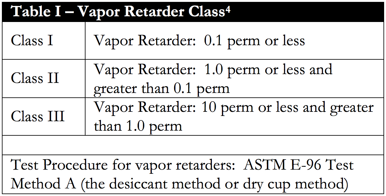
The second code is the International Residential Code (IRC). It specifies the vapor control requirements of “prescriptively” framed walls. The 2015 IRC requires a Class I or Class II vapor retarder on the interior of a framed wall assembly (see Table I for Class definitions). An exception is provided allowing a Class III vapor retarder if a wall framed with 2x4 framing has a minimum of R-10 exterior continuous insulation (R-13 + 10) or if framed with 2x6 framing must have a minimum of R-15 exterior continuous insulation (R-20 + 15). Using exterior continuous insulation provides condensation control by elevating the temperature of the condensing surface (the back side/cavity side of the sheathing). We have been here before (“BSI-049: Confusion About Diffusion”, May 2011).
The temperature of the condensing surface is controlled by the ratio of the thermal resistance exterior to the condensing surface compared to the thermal resistance to the interior of the condensing surface. A 2x6 wall needs more exterior continuous insulation to control the temperature of the condensing surface than a 2x4 wall. Hence the reason for the two different requirements in the IRC for condensation control between 2x4 framing and 2x6 framing.
In a 2x4 wall with cavity insulation of R-13 plus exterior continuous insulation of R-10 the total nominal thermal resistance is R-23. In a 2x6 wall with cavity insulation of R-20 plus exterior continuous insulation of R-15 the total nominal thermal resistance is R-35. Simple arithmetic yields the following similar ratios:
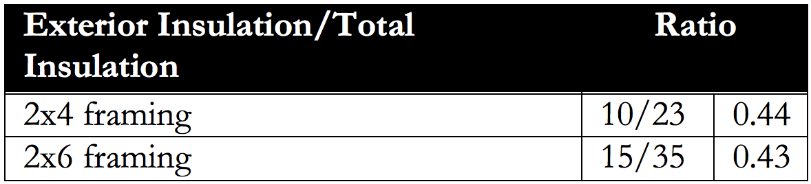
How did the IRC pick a ratio of around 0.4 for IECC Climate Zone 7? It came from me. Yup. My fault. The point was to keep the condensing surface (cavity side of the exterior continuous insulation) temperature above 40 degrees F (5 degrees C) for most of the winter. To make the arithmetic work I picked the average of the monthly average outside temperature of the three coldest months for the exterior air temperature and an interior temperature of 68 degrees F (20 degrees C).
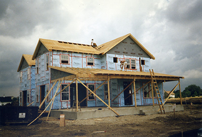
So where did the 40 degrees F (5 degrees C) come from? Trial and error and historical experience and field testing. The temperature represents the dew point temperature of 68 degrees F (20 degrees C) air at a relative humidity of 35 percent. I (and my team) spent a couple of million taxpayer dollars over a decade building test huts (Photograph 1), test buildings in the various climate zones and examining regional historic practice to develop this simple relationship.[5]
Photograph 1: Test Hut - A couple of million taxpayer dollars was spent over a decade constructing, instrumenting and managing test huts in the various climate zones.
Let’s apply this to Steamboat Springs. The average monthly exterior air temperature for the three coldest months in Steamboat Springs is:
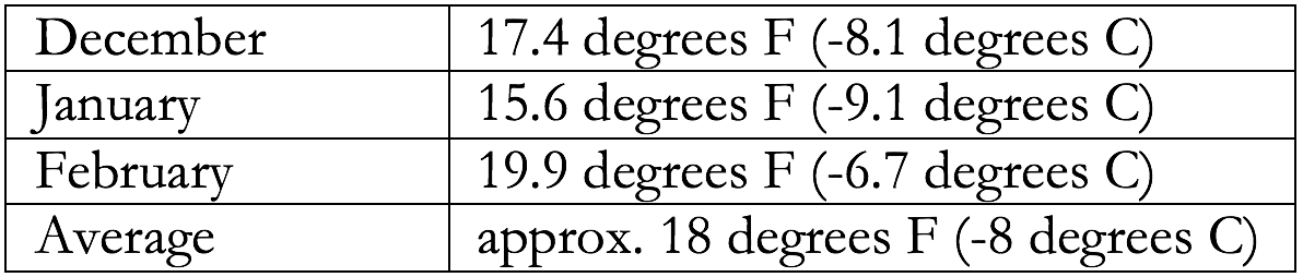
So the average temperature difference between the inside and the outside over the three coldest months is (68 minus 18) approximately 50 F degrees (28 C degrees).
Now we need to figure out the average temperature of the condensing surface over the three coldest months. Take 10/23rds of 50 and you get 22 degrees. Add 22 degrees to 18 degrees and you get 40 degrees. Ta-da! How about that? The IRC gets it right for Steamboat Springs. Note that I am patting myself on the back here. Also note that the IRC has done all the calculations for you and presented them in a table. You don’t have to do any calculations. You just have to know where you are building (that establishes the IECC Climate Zone) and whether or not you are framing with 2x4’s or 2x6’s. So stop with the dewpoint calculations already….
Let’s go back to the two code requirements. For a wall framed with 2x4’s the IECC requires (R-13 + 10) for the prescriptive minimum thermal resistance in IECC Climate Zone 7. For a wall framed with 2x4’s the IRC requires (R-13 + 10) for condensation control when using a Class III vapor retarder. How about that? Both requirements are the same for 2x4 framing. Note that the IRC does not prevent you from using either a Class I or Class II vapor retarder as well when framing with 2x4’s.
However, when we frame the wall with 2x6’s the IECC requires (R-20 +5) for the prescriptive minimum thermal resistance in IECC Climate Zone 7 whereas the IRC requires (R-20 – 15) for condensation control when using a Class III vapor retarder. You want to stay with the (R-20 + 5)? OK, then you need a Class I or Class II vapor retarder. Don’t want a Class I or Class II vapor retarder? OK, then you need to up the thermal resistance of the exterior continuous insulation. This is not a complicated code issue.
Let me restate it a little differently. With 2x4 framing in Steamboat Springs you can use a Class I or Class II or Class III vapor retarder and not be in conflict with either the IECC or the IRC. Pick one. With R-10 exterior continuous insulation all three work just fine. With 2x6 framing you can use Class I or Class II wherever you want. However, with Class III you need to go to R-15 exterior continuous insulation or higher to make things work under the IRC.
So what’s the problem? Well, folks are not used to building with exterior continuous insulation in Steamboat…or in lots of other places for that matter. Until the 2015 IECC and 2015 IRC were adopted that standard way of building exterior walls in Steamboat did not utilize exterior continuous insulation (Figure 1). The “wall du jour” was a 2x6 wall framed with oriented strand board (OSB) and a 6 mil polyethylene vapor barrier on the inside (Photograph 2). The polyethylene vapor barrier is considered a Class I vapor retarder. Everyone was happy with this. The builders, the code officials, the lift operators and the bartenders, everyone. The wall could dry to the exterior if it got wet.
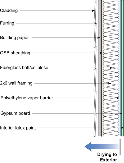
Figure 1: “Wall Du Jour” - 2x6 wall framed with oriented strand board (OSB) and a 6 mil polyethylene vapor barrier on the inside. The polyethylene vapor barrier is considered a Class I vapor retarder. Everyone was happy with this. The builders, the code officials, the lift operators and the bartenders, everyone. The wall could dry to the exterior if it got wet.
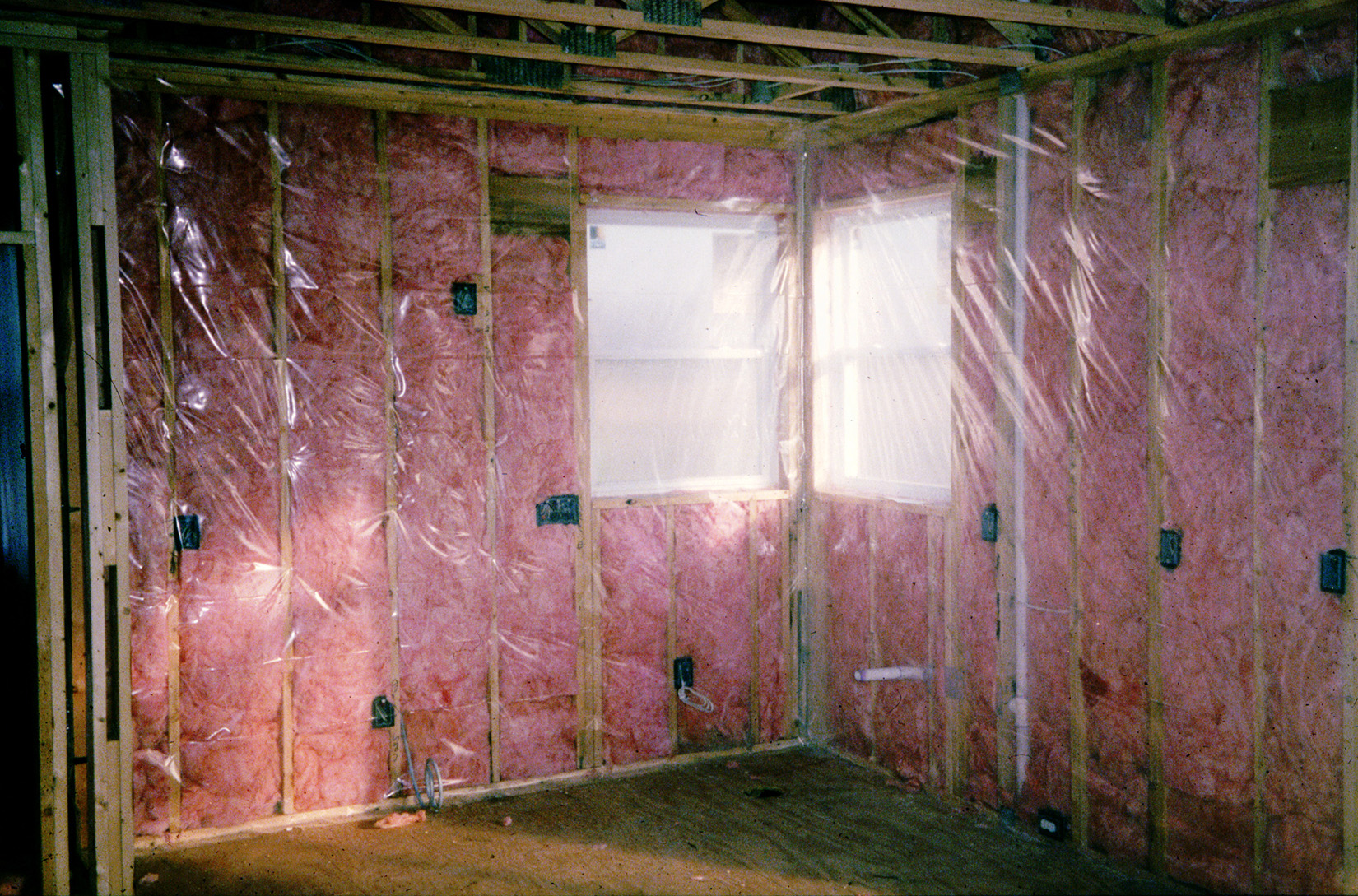
Photograph 2: Polyethylene Vapor Barrier – a “classic” Class I vapor retarder. Also a pretty darn good air control layer when installed with fastidious care…
Although it was not common, you could also install a Class II vapor retarder on the inside of the wall framing if you wanted to avoid the poly and still meet the code requirement for condensation control (Figure 2). The typical Class II vapor retarder was (and still is) a kraft faced fiberglass batt (Photograph 3). The Class II vapor retarder allowed inward drying in the summer time (we were here before as well, see Figure 4 from “BSI-092: Doubling Down-How Come Double Vapor Barriers Work?”, February 2016).
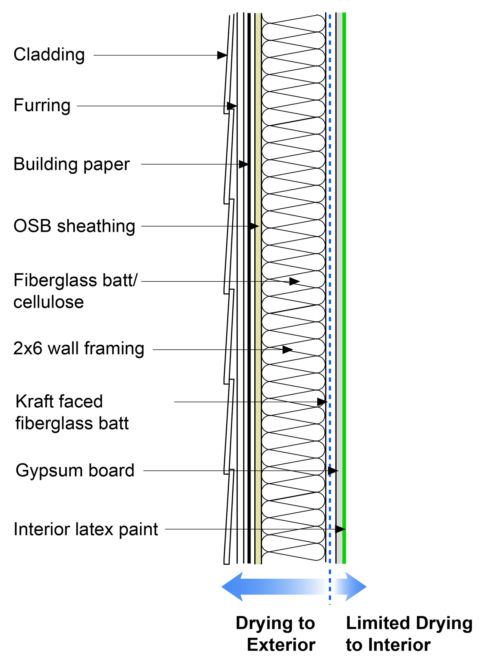
Figure 2: Class II Vapor Retarder - Although it was not common, you could also install a Class II vapor retarder on the inside of the wall framing if you wanted to avoid the poly and still meet the code requirement for condensation control.
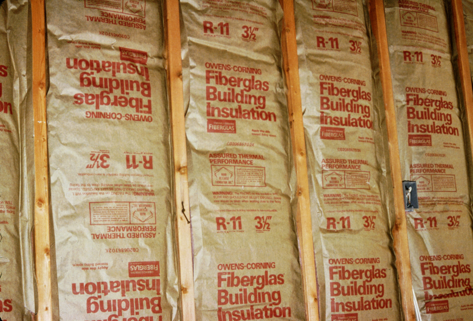
Photograph 3: Kraft-Faced Fiberglass Batts - The typical Class II vapor retarder was (and still is) a kraft faced fiberglass batt. The Class II vapor retarder allows inward drying in the summer time.
Well, all that changed with the adoption of the 2015 codes. The builders had to use exterior continuous insulation. The big fear was would that prevent the walls from being able to dry to the exterior? Not if you used a vapor open exterior continuous insulation like stone wool/mineral fiber rigid insulation (Figure 3). If you used a vapor closed exterior continuous insulation like extruded polystyrene (Photograph 4) drying to the exterior was not possible. But drying to the interior was possible if you used enough exterior continuous insulation coupled with a Class III vapor retarder (Figure 4). We talked about this possibility already. Ah, but the R-15 required meant about 2.5 inches to 3 inches of exterior insulation and that was a pain. Not a lot of joy from the builders. Even the lifties and barflies were irritated.
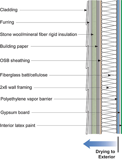
Figure 3: Vapor Open Exterior Continuous Insulation - Stone wool/mineral fiber rigid insulation allows drying to the exterior.
Photograph 4: Vapor Closed Exterior Continuous Insulation - If you used a vapor closed exterior continuous insulation like extruded polystyrene drying to the exterior was not possible.
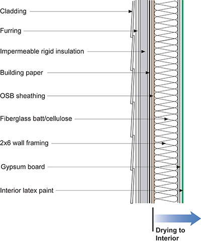
Figure 4: Interior Drying - Drying to the exterior is not possible with vapor closed exterior continuous insulation. But drying to the interior is possible if you use enough exterior continuous insulation coupled with a Class III vapor retarder.
Nothing however prevented anyone from using R-5 vapor closed insulation with 6 mil polyethylene on the inside (Figure 5). Yes, but that “creates” the evil double vapor barrier. Yes, but it has been shown to work all over the place. Relax. And again, as noted already, we have been here before (“BSI-092: Doubling Down-How Come Double Vapor Barriers Work?”, February 2016). But, apparently folks are unable to relax. So now what?

Figure 5: Double Vapor Barrier - Nothing however prevents anyone from using R-5 vapor closed insulation with 6 mil polyethylene on the inside. Yes, but that “creates” the evil double vapor barrier. Yes, but it has been shown to work all over the place. Relax. And again, as noted already, we have been here before (“BSI-092: Doubling Down-How Come Double Vapor Barriers Work?”, February 2016). But, apparently folks are unable to relax.
Easy, replace the 6 mil polyethylene with a kraft faced fiberglass batt and keep the R-5 vapor closed exterior continuous insulation. Replace the Class I vapor retarder with a Class II vapor retarder. The IRC allows you to do this. Well, amazing as it seems, folks really like their 6 mil polyethylene in Steamboat. Go figure.
So can we make folks a little bit more comfortable with the 6 mil poly on the inside and the vapor closed exterior continuous insulation on the outside? Yes, of course. A little bit of magic and cleverness can come into play.
Back in the day, we found that cutting grooves into the continuous insulation (Photograph 5) or placing the continuous insulation over textured building papers (Photograph 6) to facilitate drainage also provided redistribution of moisture when the exterior continuous insulation was vapor closed (Photograph 7). (And, yes, we were also here earlier…“BSI-071: Joni Mitchell, Water and Walls”, November 2013).
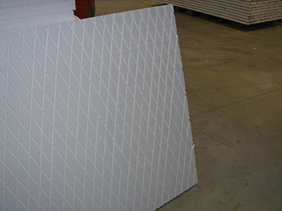
Photograph 5: “Groovy” - Cutting grooves into the continuous insulation to facilitate drainage also provides redistribution of moisture.
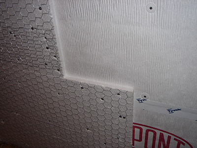
Photograph 6: Textured Building Papers - Placing the continuous insulation over textured building papers to facilitate drainage also provides redistribution of moisture.
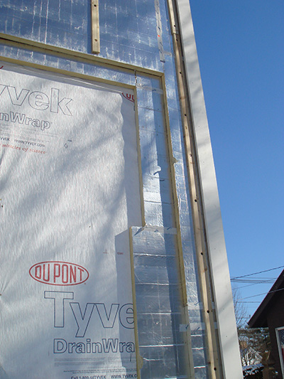
Photograph 7: Vapor Closed Foil Faced Continuous Exterior Insulation – Note the draining building wrap providing redistribution of moisture. And, yes, we were also here earlier…“BSI-071: Joni Mitchell, Water and Walls”, November 2013).
We found that it did not take much to provide the drying to the exterior via lateral diffusion and some airflow – gaps of 1/32 to 1/16 of an inch had a huge positive benefit. Note that the spacing needed to be small to limit the reduction in thermal performance of the exterior continuous insulation.[6] Cap nails or washers proved to be pretty effective spacers (Photograph 8). This “rain screen” technology eventually led to the development of the “beer screen” (Photograph 9)…..So folks in Steamboat, keep that “chug, chug” thing going….
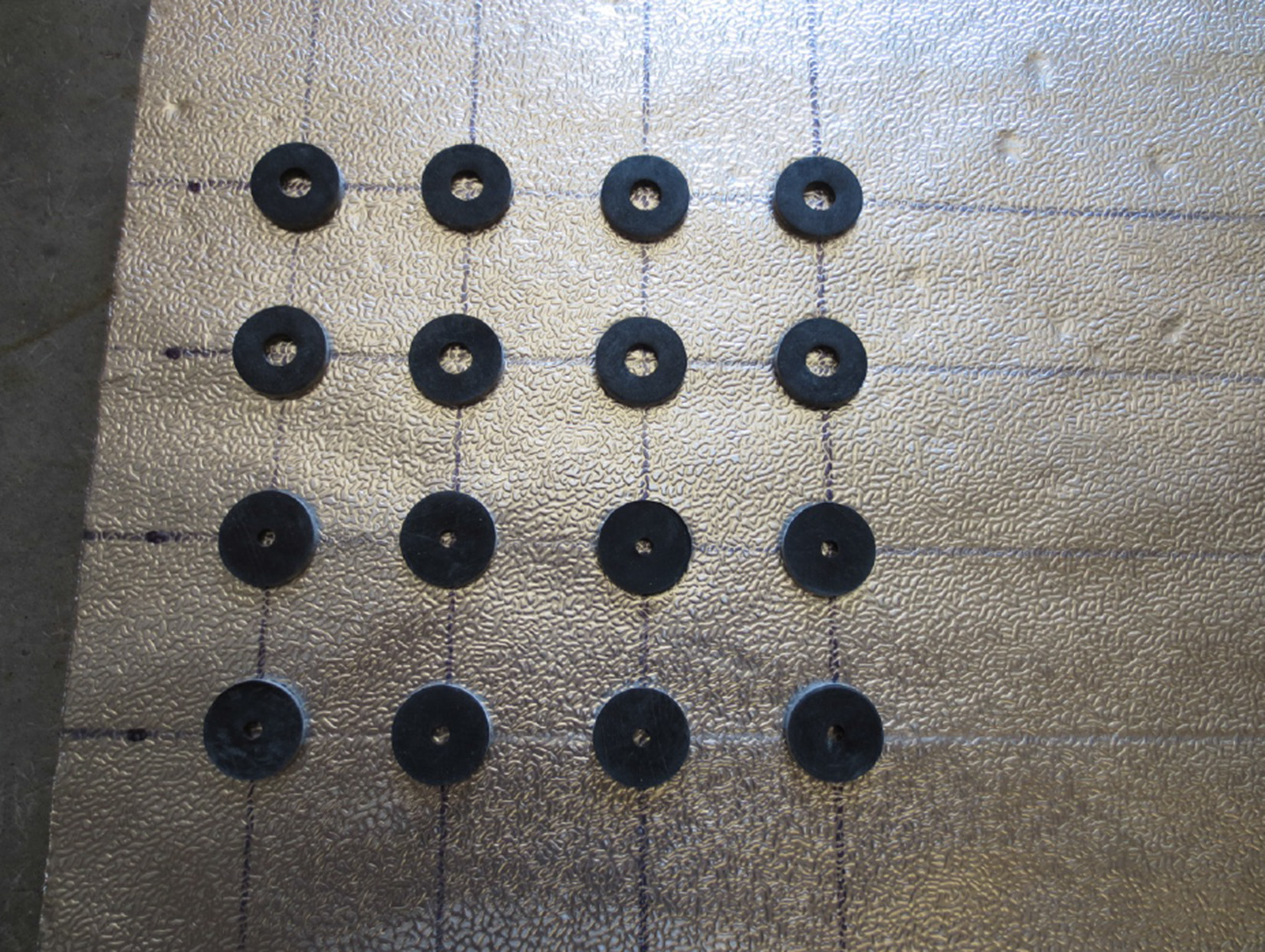
Photograph 8: Cap Nails/Washers - Gaps of 1/32 to 1/16 of an inch have a huge positive benefit. Note that the spacing needed to be small to limit the reduction in thermal performance of the exterior continuous insulation.
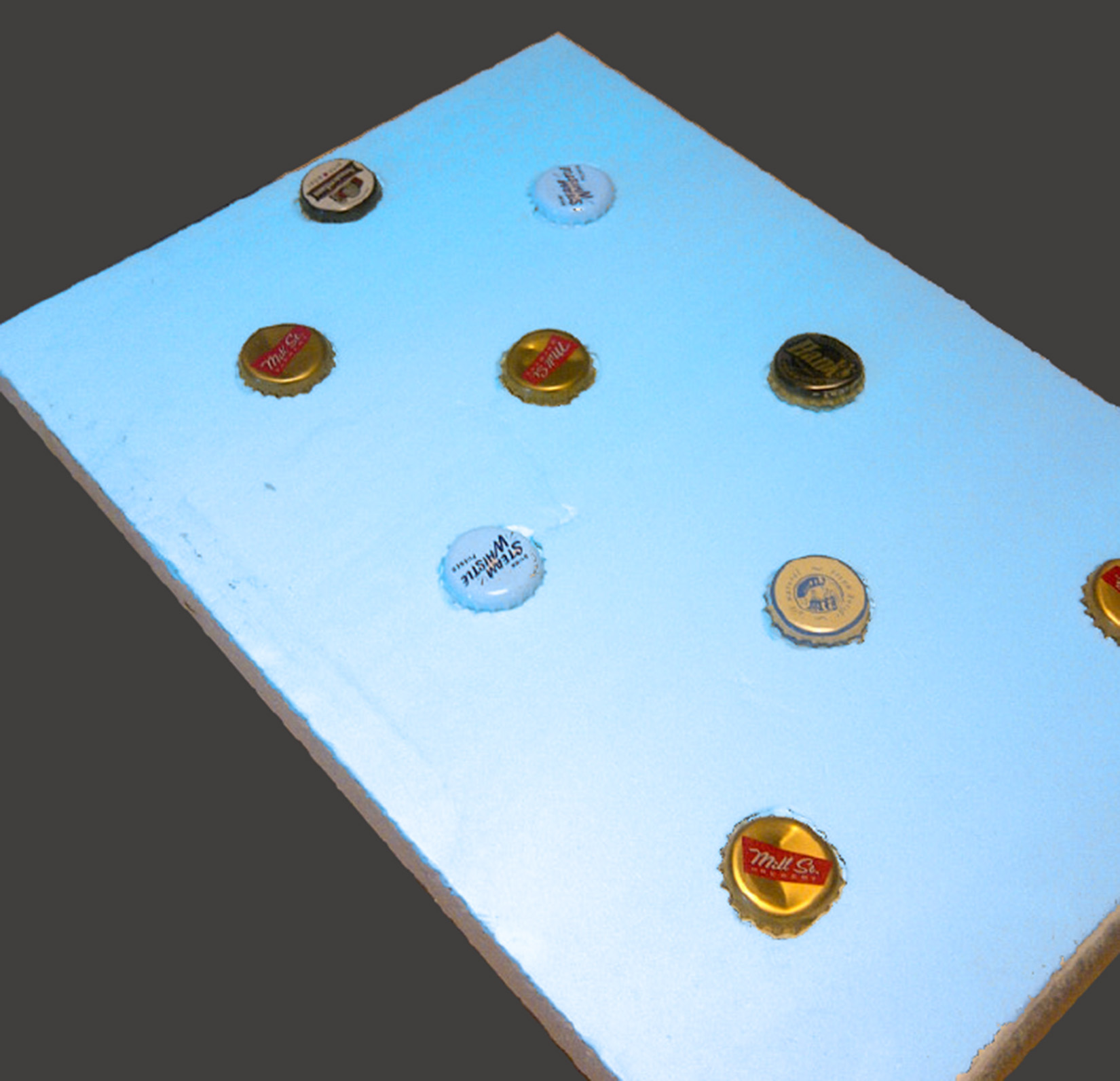
Photograph 9: Beer Screen - The “rain screen” technology eventually led to the development of the “beer screen”…..
Ha, ha, ha!
Who’s got the last laugh now?
[1] Denis Papin, Thomas Newcomen and James Watt.
[2] Fulton was a pretty amazing guy. A guy born on a farm in Pennsylvania who was commissioned by Napoleon Bonaparte to design the first practical submarine, the Nautilus, when he was not painting portraits and landscapes and designing torpedoes for the British Royal Navy. Yes, that “Nautilus”. An American “Leonardo”…not DiCaprio, the real one. The Beach Boys memorialized him in their song “Steamboat….Don’t worry mister Fulton, We’ll get your steamboat rollin…” Thank you Dennis Wilson.
[3] ”juju” is a spiritual belief system incorporating objects and spells used in religious practice as part of witchcraft emanating in West Africa currently being applied to wall assemblies by building officials in North America.
[4] Lstiburek, J.W., “Understanding Vapor Barriers”, ASHRAE Journal, August, 2004.
[5] The U.S. Department of Energy funded the research through the Building America Program.
[6] I am not allowed to tell you how I know this for reasons I can’t get into…but trust me on this….you need to keep the gap less than 1/8 inch to limit the loss in thermal performance of the exterior continuous insulation below 5 percent….which is less than the loss in thermal performance that occurs due to the thermal bridging associated with attaching the cladding and continuous insulation itself….