Claddings and trim get the most stress imaginable next to roofing. They get rain and sun and go through huge temperature swings. Recognize these stressors? The principle “damage functions” of water, heat and ultra violet radiation. People such as clients want claddings and trim to last and look good. Crazy, eh? Getting paint to stick to wood claddings and trim was hard enough in the old days. Now we want it to stick not only to wood, but to engineered wood, fiber cement and other composites. Even worse, we have changed the energy balance and the underlying materials and layers to make everything more difficult.
The good news is what we learned about wood back in the day[1] also applies to engineered wood and other composites.
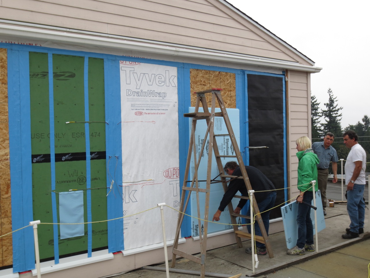
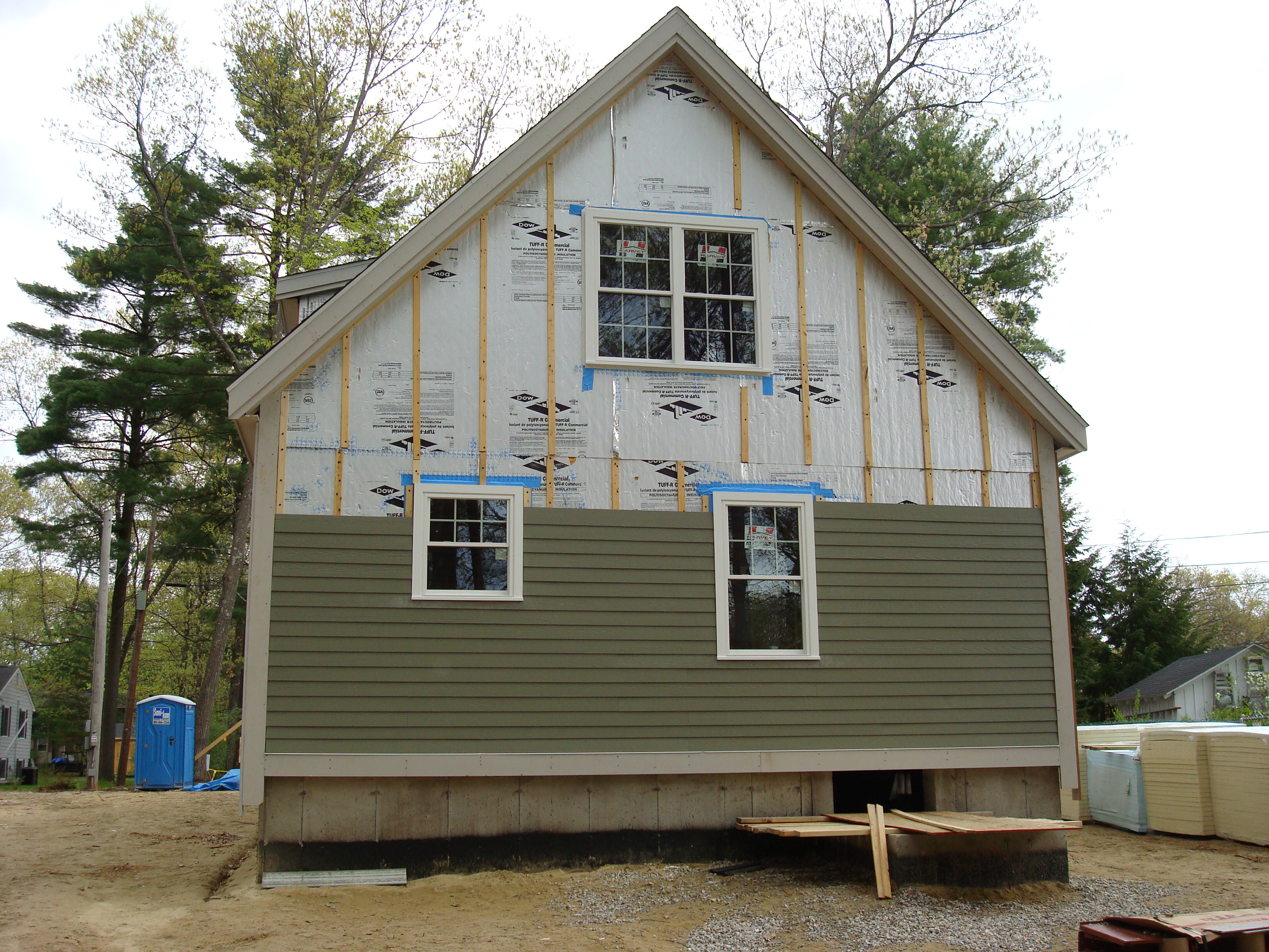
The bad news is that we have to change cladding and trim practices to make things last and look good in highly insulated wall assemblies constructed with modern sheathings such as oriented strand board (OSB) and foam plastic such as extruded polystyrene (XPS) and foil faced isocyanurates. And oh yeah, “tar paper” is a fading memory in the age of modern building wraps, fluid applied coatings and fully adhered membranes. The days of tar paper and plywood in a poorly insulated wall are long gone.
Back to some good news…. we have spectacular paints and coatings that are vapor permeable, retain their flexibility and are resistant to ultra violet light. Having said that, they are not spectacular enough to compensate for the energy balance and the change in materials. We can’t just rely on modern coatings to keep us out of trouble with claddings and trim.
The solution is quite simple – coat all six sides of claddings and trim and then back ventilate – but to appreciate why this works we have to go back and understand how we got to this point. And the details of how we actually do this are not always easy.
It is also important to note that back ventilation of claddings and trim results in an airspace that provides a huge benefit in rainwater entry as it controls hydrostatic pressure along with providing another huge benefit in enhancing outward drying of the wall assemblies themselves compensating for the change in energy balance. So we get a “three-for-one” – control of hydrostatic pressure, enhanced assembly drying as well as a huge stress release to the claddings and trim.
 Photograph 1: Bad Paint - The paint looks bad, real bad, but there is no decay. This is an old uninsulated wood frame building. Board sheathing, asphalt impregnated felt building paper. Wood clapboard siding and wood trim. Oil based primer and oil based paint. Water is getting behind the wood siding and trim via capillarity. The water can’t evaporate outward through the impermeable paint film.
Let’s start the story by looking at Photograph 1. A couple of things you need to know with this image. The paint looks bad, real bad, but there is no decay. This is an old uninsulated wood frame building. Board sheathing, asphalt impregnated felt building paper. Wood clapboard siding and wood trim. Oil based primer and oil based paint. Water is getting behind the wood siding and trim via capillarity (Figure 1). The water can’t evaporate outward through the impermeable paint film. The only drying is inward. The moisture content in the wood siding and trim cycles due to incident solar radiation and heat loss from the building. The moisture content cycling causes expansion and contraction in the wood causing the paint film to be stressed leading it to fail. If the paint had been a modern vapor open (permeable) and flexible acrylic latex none of this would have happened. The amount of wetting could have been handled by the paint characteristics alone. Lots of available energy to dry both inwards and outwards. The felt building paper and the wood board sheathing allow inward redistribution of moisture. So, the easy fix for this problem is to scrape the paint down to bare wood, prime with an oil based primer and topcoat with an acrylic latex paint.
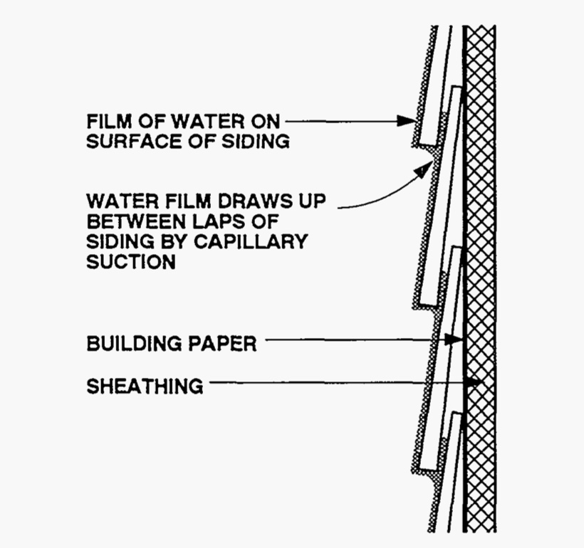 Figure 1: Capillary Rise In Siding – This image comes from the DOE Moisture Control Handbook, circa 1989, not much has changed.
Why an oil based primer? Aren’t oil based (or alkyd) coatings vapor retarders? Yes. But we have another problem to deal with. Water based primers have issues with water soluble extractives such as tannins and wood sugars in wood siding and trim. That’s why we prime with alkyds sealing the surface preventing the migration of tannins and water soluble extractives into the water based acrylic latex topcoats.
But this easy fix runs into problems if we are unable to redistribute some of the moisture inwards. Old walls had board sheathing and felt paper and could absorb inwardly driven moisture. Replace the board sheathing with OSB and a modern plastic housewrap and the moisture remains more concentrated at the back side of the siding and trim at the housewrap/OSB interface. This increases the stress on the paint film as the moisture cycling increases in both frequency and amplitude – and yes the paint fails. But typically no decay. That changes when we add insulation.
Insulation reduces heat loss and increases the dwell time for moisture at the overlaps of wood siding and at joints between trim and siding. The colder the siding, the higher the relative humidity at the surfaces. Wood moisture content is directly related to relative humidity. The higher the relative humidity the higher the moisture content.
Photograph 2 and Photograph 3 shows the effect of increasing the dwell time for moisture at the overlaps of siding. The “classic” means of addressing this issue is to reduce the capillary absorption at the overlaps and joints by “back priming” or “back coating” the back surfaces of the siding.
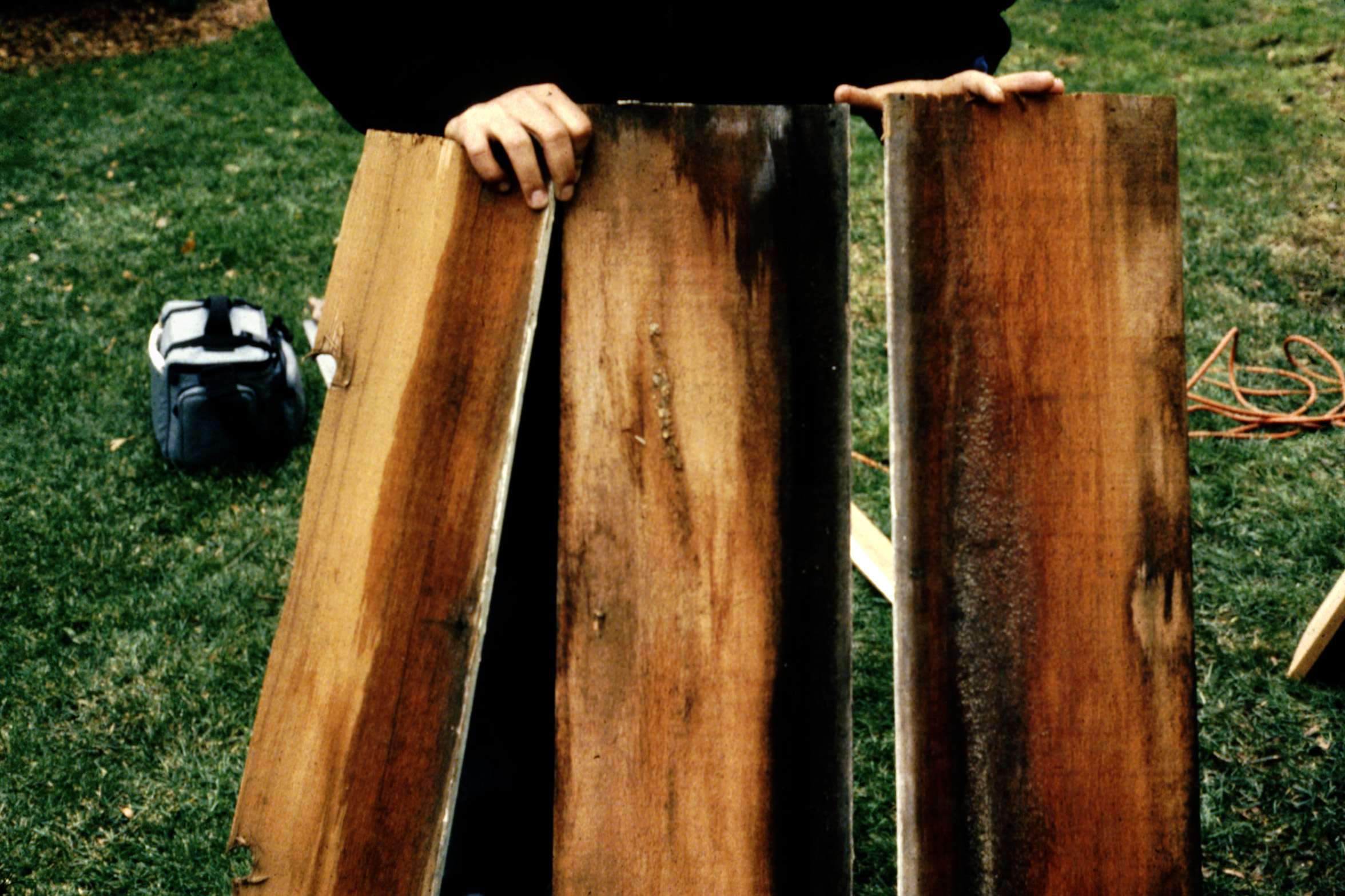 Photograph 2: Capillary Wetting - The effect of increasing the dwell time for moisture at the overlaps of siding. The “classic” means of addressing this issue is to reduce the capillary absorption at the overlaps and joints by “back priming” or “back coating” the back surfaces of the siding.

Photograph 3: More Capillary Wetting – This is more of a cold climate issue than a warm climate issue. Inward drive in warm climates increases the drying of the cladding. Of course this assumes that the inwardly driven moisture can go somewhere…like into absorptive building papers and sheathings.
Over time coating of the back surfaces of siding was extended to the cut ends of siding and trim. Wood is anisotropic…it absorbs water differently based on the grain/fiber direction. Cut ends absorb way more water than the face of siding and trim. Painting of cut ends became necessary to control decay of wood and wood based claddings as it reduced water absorption (Photograph 4).
 Photograph 4: Sealing End Cuts - Over time coating of the back surfaces of siding was extended to the cut ends of siding and trim. Wood is anisotropic…it absorbs water differently based on the grain/fiber direction. Cut ends absorb way more water than the face of siding and trim. Painting of cut ends became necessary to control decay of wood and wood based claddings as it reduced water absorption.
Cut ends proved to be particularly sensitive to water absorption particularly at wall-to-roof interfaces (Photograph 5). Sealing cut ends coupled with an air gap became the norm.
 Photograph 5: Faith Based Water Control – Sloping end cuts not sealed where the cladding intersects the sloping roof. Worse, no air gap between the end cuts and the sloping roof. A minimum 2 inch gap is necessary.
Trim elements tended to be the “weak link” as they tended to be adjacent to the most joints hence the most cut ends and exposed fibers. Where they butted into other elements or components or other trim pieces capillary absorption tended to be enhanced (Photograph 6). Sealing/painting cut ends, back coating and adding an air gap to act as a capillary break became necessary (Photograph 7). The approach evolved into coating “all six surfaces” (Figure 2) coupled with air gaps between intersecting components such as decks and roofs.
 Photograph 6: Trim Issues - Trim elements tended to be the “weak link” as they tended to be adjacent to the most joints hence the most cut ends and exposed fibers. Where they butted into other elements or components or other trim pieces capillary absorption tended to be enhanced.
 Photograph 7: Trim Gap - Sealing/painting cut ends, back coating and adding an air gap to act as a capillary break became necessary.
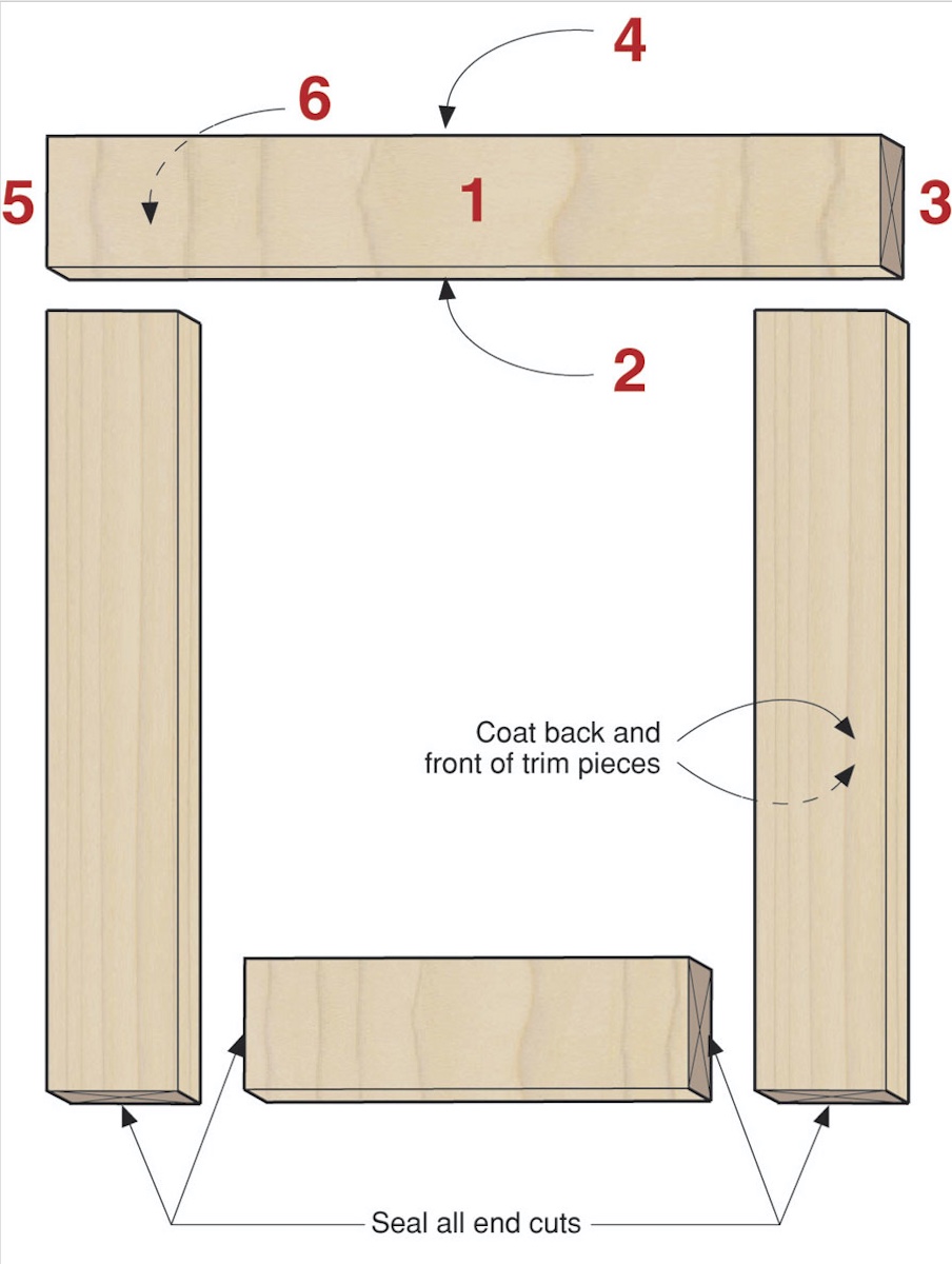
Figure 2: Trim Details - Seal or coat all six surfaces of materials to limit water absorption. Back ventilate trim materials so that absorbed water can evaporate and be vented to the exterior.
Coating all six surfaces dramatically increased performance of coating systems as it reduced water absorption. But the approach did not address the reduced ability of the assemblies to redistribute moisture inwards. The old felt papers provided a reservoir to take inwardly driven moisture as did plywood and board sheathings. As they were replaced with plastic building wraps, OSB and foam plastic such as extruded polystyrene (XPS) and foil faced isocyanurates inward moisture redistribution was not possible. In hot humid climates this became a big deal due to the inward drive due to solar radiation. You can’t push moisture out of the back side of cladding into a layer of plastic or aluminum foil.
Paint problems reoccurred with a vengeance. The solution was of course obvious – an air gap. The air gap essentially uncouples the cladding and the trim from the rest of the wall assembly. But how much of a gap?
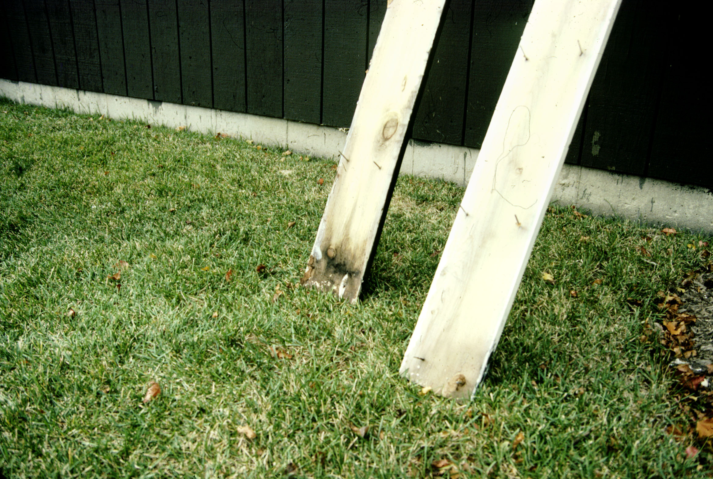
Being an old school engineer the approach to figure this out was obvious – guess – and test to failure (Photograph 8 and Photograph 9). Apparently, somewhere between 1/4 inch and 3/8 inch works well with wood and engineered wood based claddings and trim along with fiber cement cladding and trim components.
 Photograph 8: Test Hut Stress – You can’t calculate this. Being an old school engineer the approach to figure this out was obvious – guess – and test to failure.
 Photograph 9: More Test Hut Stress - Apparently, somewhere between 1/4 inch and 3/8 inch works well with wood and engineered wood based claddings and trim along with fiber cement cladding and trim components.
Today virtually all wood trim and engineered wood claddings, fiber cement and composites come coated on all six sides or protected on all six sides (Photograph 10). But not all trim and claddings are installed over air gaps. As previously stressed the gap is necessary in high performance assemblies. So how to do this?
 Photograph 10: Modern Trim - Today virtually all wood trim and engineered wood claddings, fiber cement and composites come coated on all six sides or protected on all six sides.
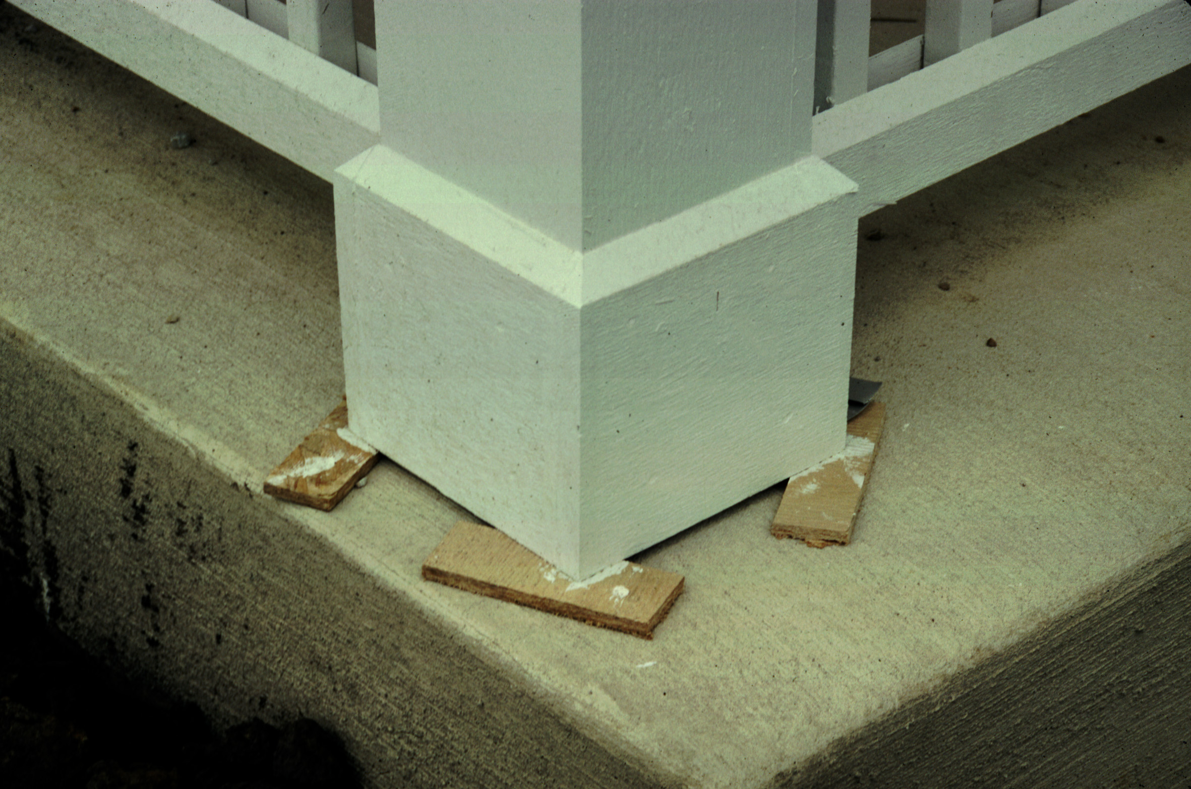
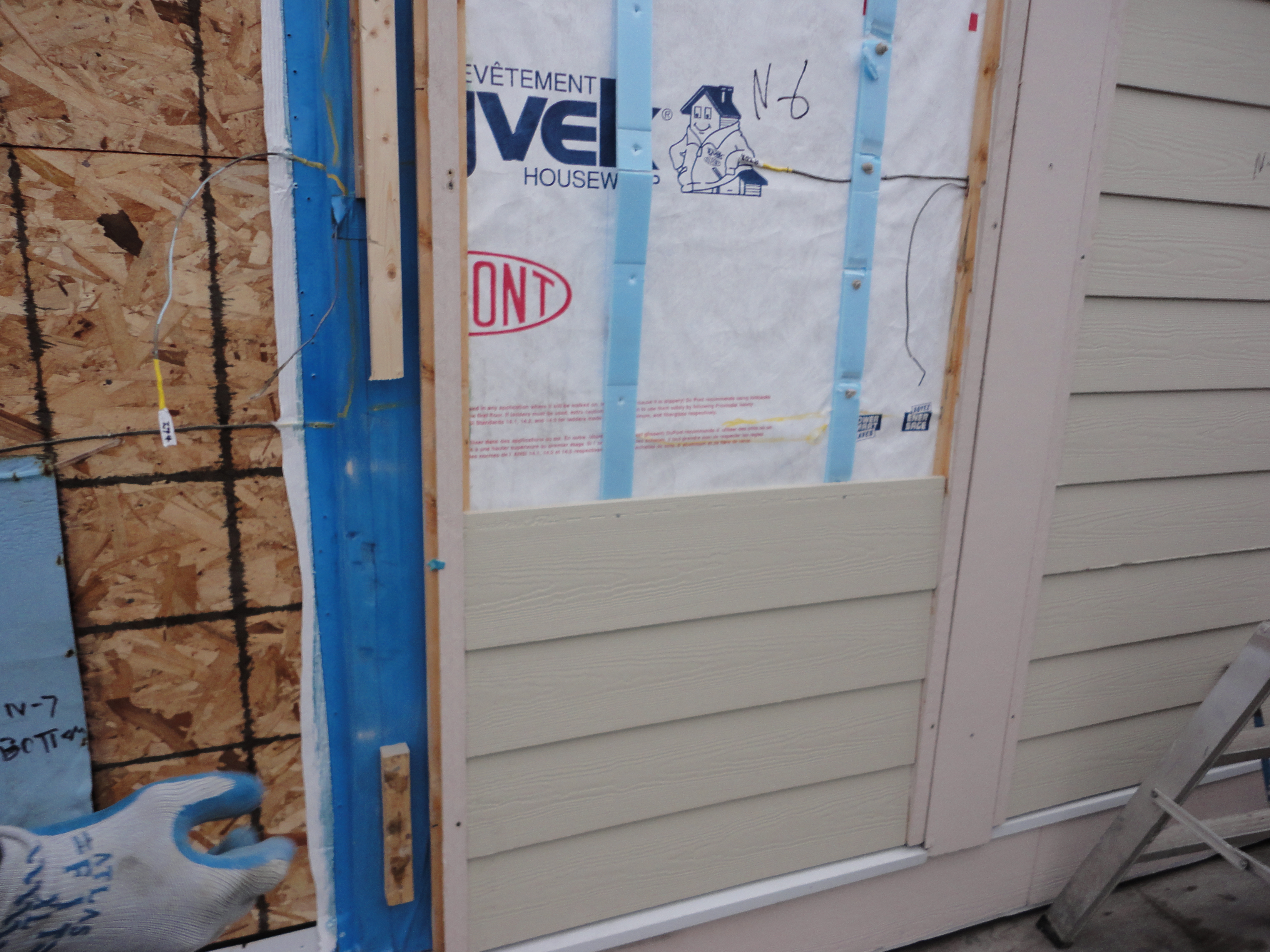
Figure 3 and Photograph 11 show how to do it with OSB and with continuous insulation less than 1 1/2 inches thick. The spacer strips are 1/4 inch to 3/8 inch strips of foam or sill gasket material. No issues. Easy.
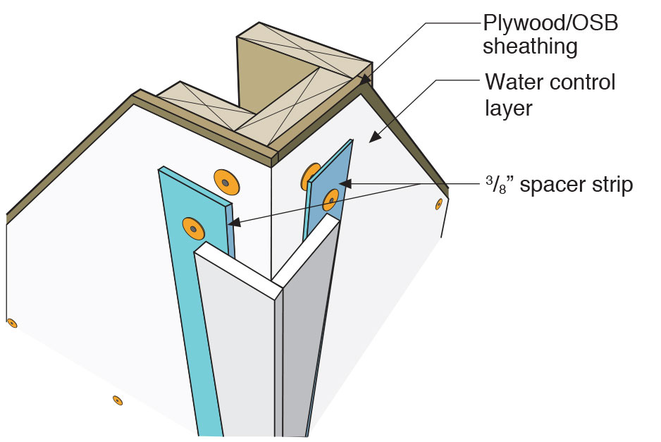
Figure 3: Air Gap – OSB and plastic housewrap. The spacer strips are 1/4 inch to 3/8 inch strips of foam or sill gasket material.
 Photograph 11: Air Gap – Not complicated with continuous insulation less than 1 1/2 inches thick. The spacer strips are 1/4 inch to 3/8 inch strips of foam or sill gasket material. No issues. Easy.
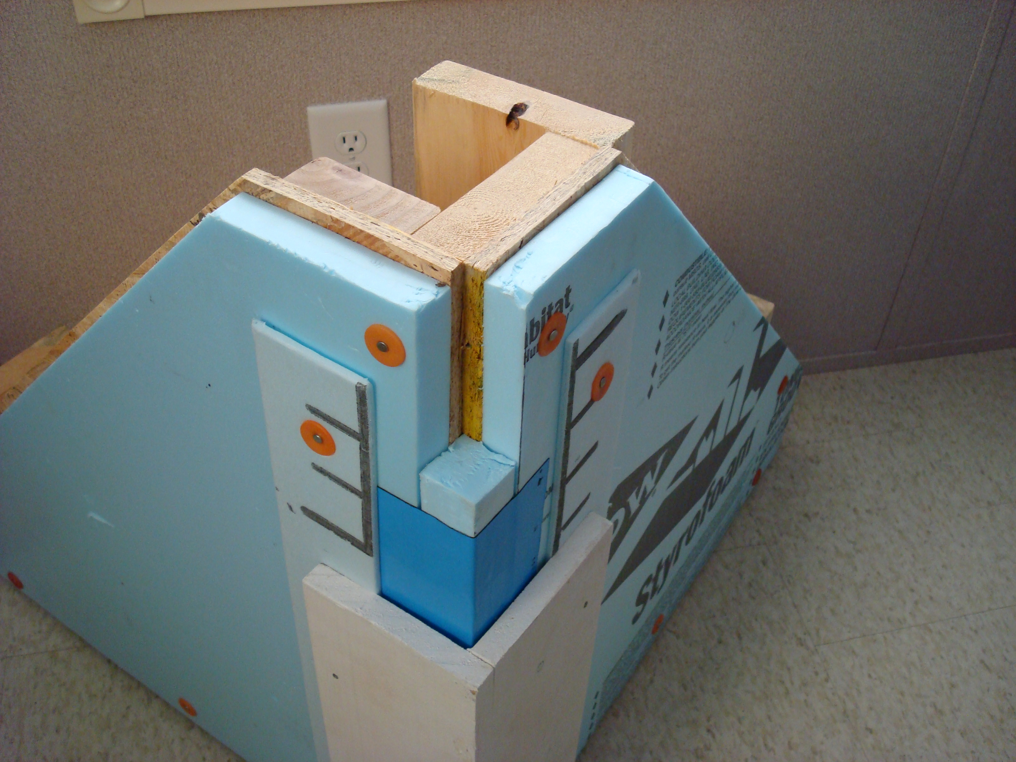
When you get to thicker layers of continuous insulation things get more complicated. You are pretty much limited to furring strips of 1x4 wood and long wood screws. Epoxy coated steel works well (Photograph 12). Thinner wood furring and the furring splits….ask me how I know? Figure 4 lays out the steps to install back vented trim and siding on a high performance wall with multiple layers of continuous insulation.
 Photograph 12: Wood Furring - When you get to thicker layers of continuous insulation things get more complicated. You are pretty much limited to furring strips of 1x4 wood and long wood screws. Epoxy coated steel works well.
The air gap should be open both at the bottom and top of the wall. The top of the wall can be vented into the soffit assembly. The bottom of the wall needs to be screened to control insect entry. Because the cladding and trim on one side of the air gap and the building wraps and sheathings on the other side of the air gap are significantly drier, insects tend to stay away.
So where are we now? The most effective way to reduce “stress” on claddings and trim is to coat or protect all six sides and to back ventilate. This works for all cladding and trim materials: wood, engineered wood, fiber cement and composites. Reduce water absorption and uncouple the materials with an air gap from the rest of the assembly. Works in all climates. Better than taking a valium.
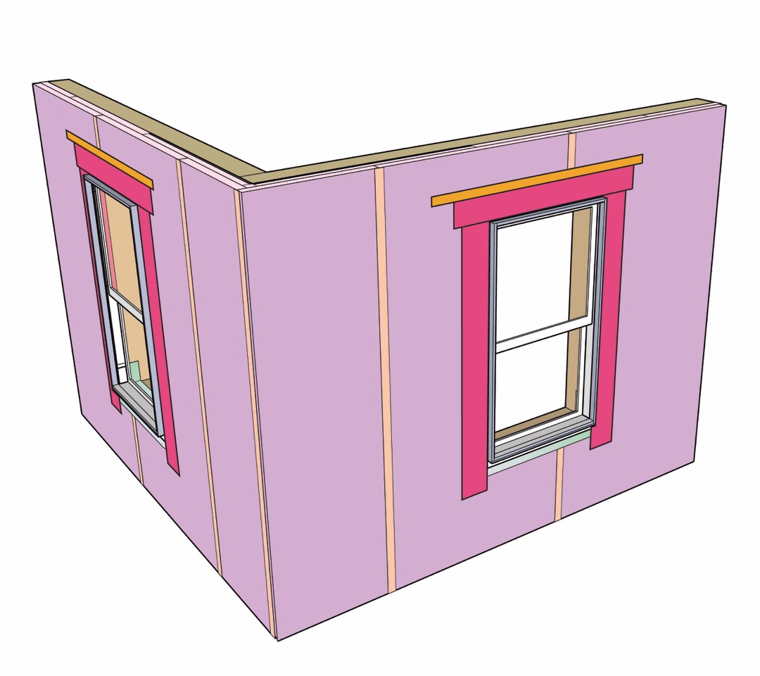 Figure 4a: Continuous Exterior Insulation – Water control layer is the exterior face of the insulation. Note the taped joints.
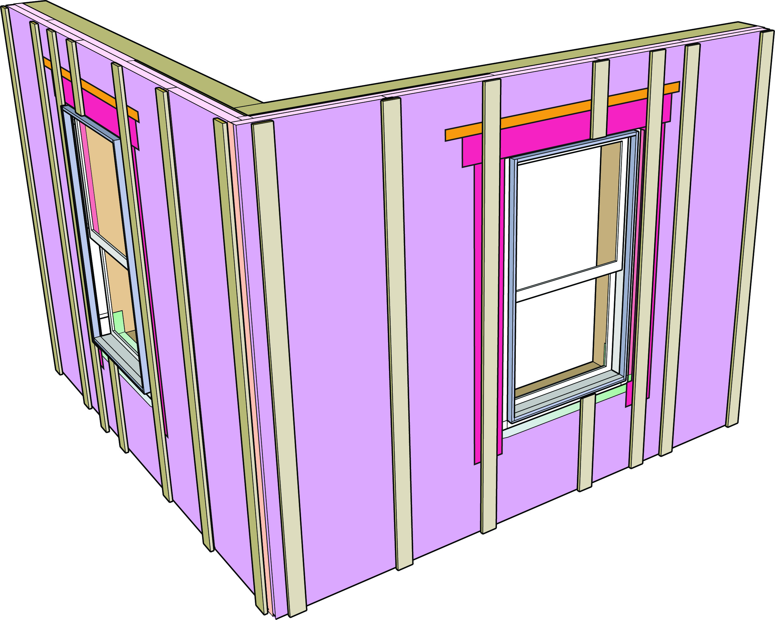
Figure 4b: Furring Strip Spacers – Note the corner geometry of the wood furring. The furring is gapped laterally at the corner.
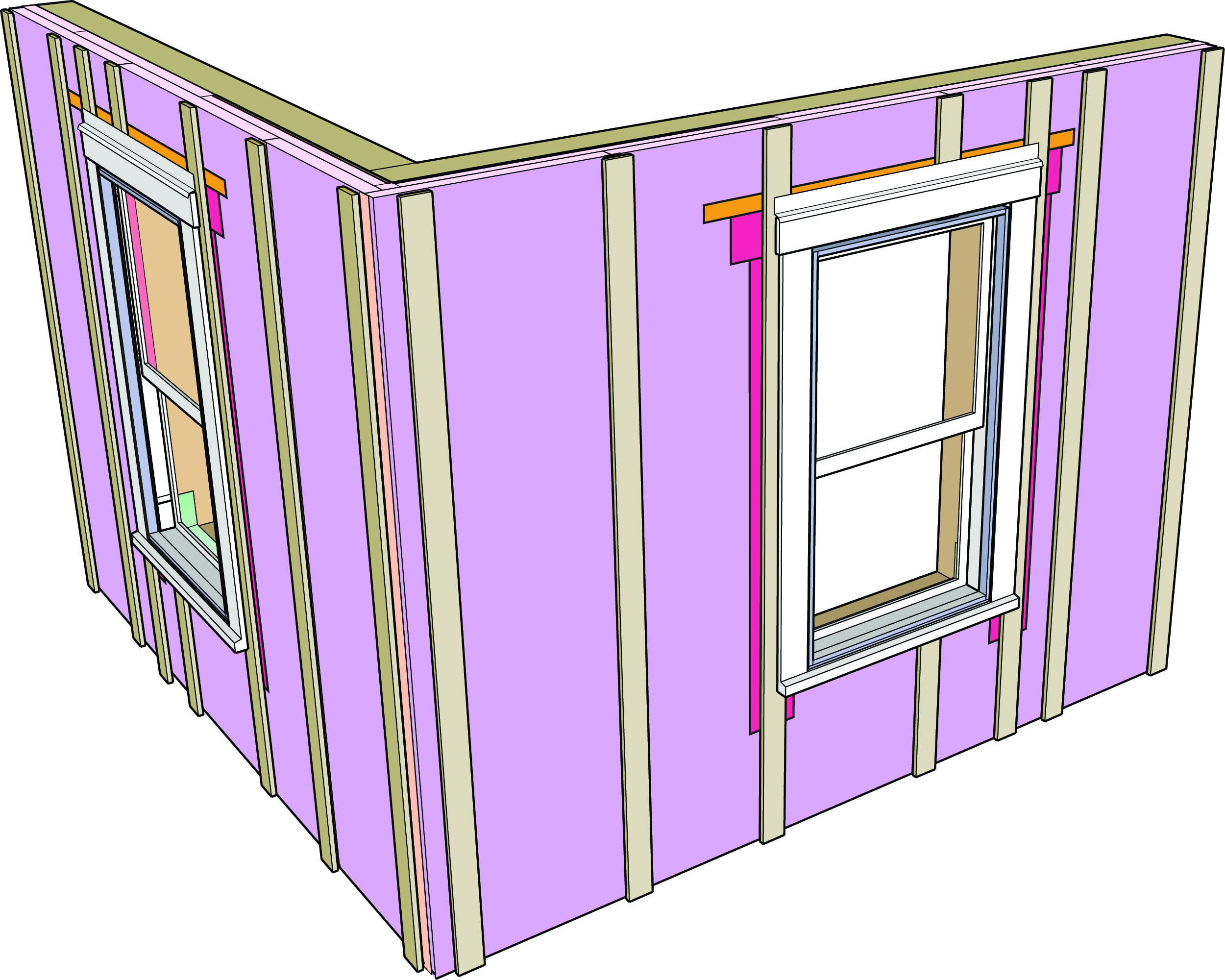
Figure 4c: Window Trim Installed – Note that the flashing above the horizontal trim at the top of the window is installed to protect the trim not to protect the window unit.
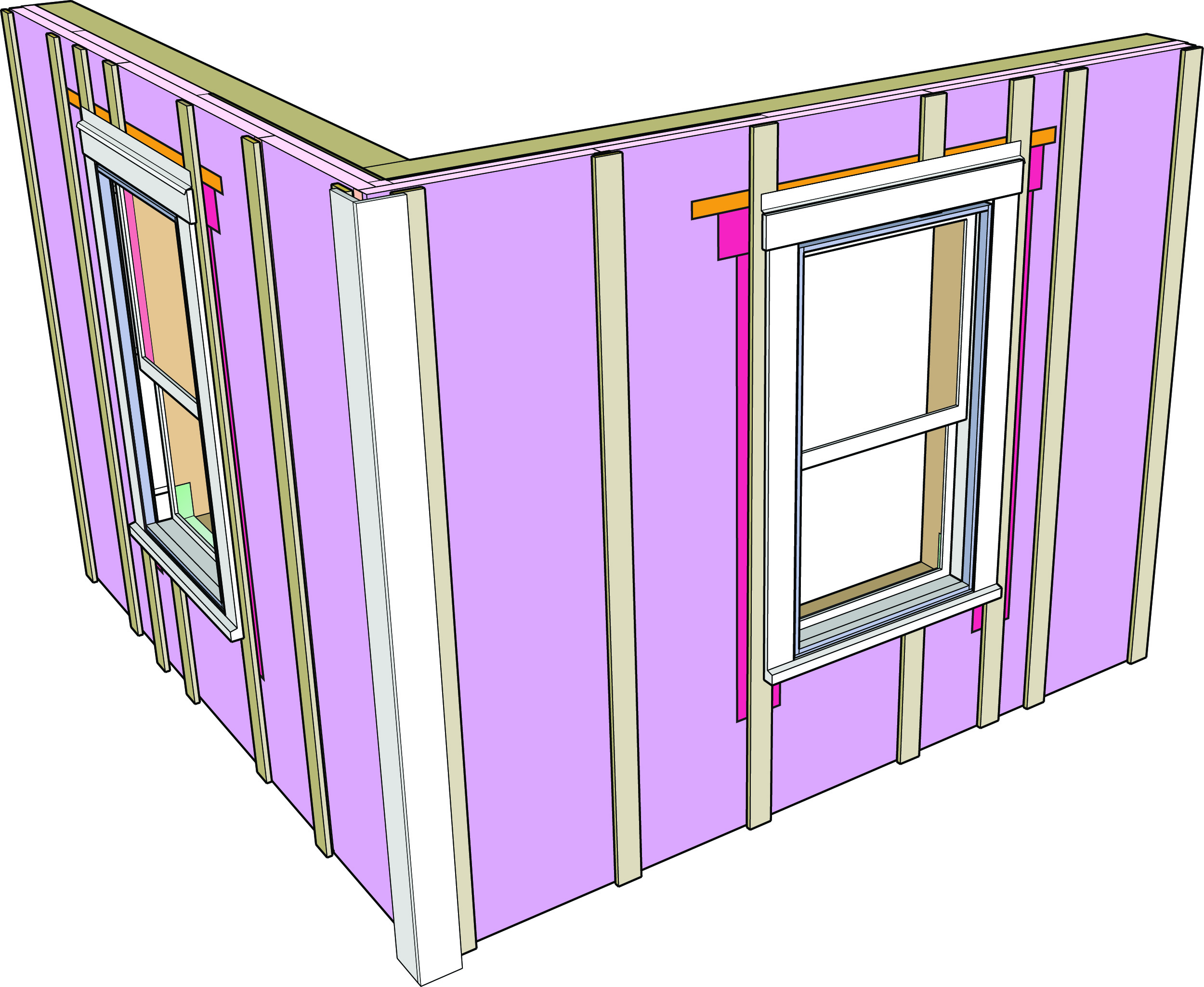
Figure 4d: Corner Trim Installed – The two corner trim pieces are attached “to themselves” and then the “L-shaped” trim assembly is attached to the gapped wood furring at the corner.
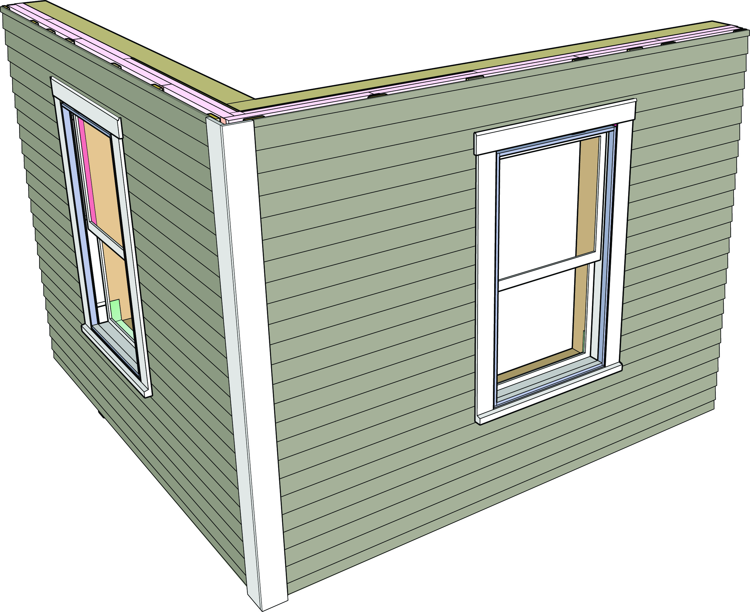
Figure 4e: Cladding Installed – Sealed on all six sides over an air gap. Awesome.