The Thermal Metric (TM) project was initiated in 2007 to support good design and construction practices by improving the way thermal performance is measured. Ultimately, the project goal is to develop a metric that can capture the in-service thermal performance of whole assemblies. More accurate measurements will allow truly high-performance assemblies (of all types of construction and insulation materials) to be identified and promoted.
The TM project is supported by the TM consortium, a group of insulation manufacturers, and led by BSC. Previous research has identified multiple factors that contribute to thermal performance: primarily thermal bridging, temperature effects, and air flow interactions.
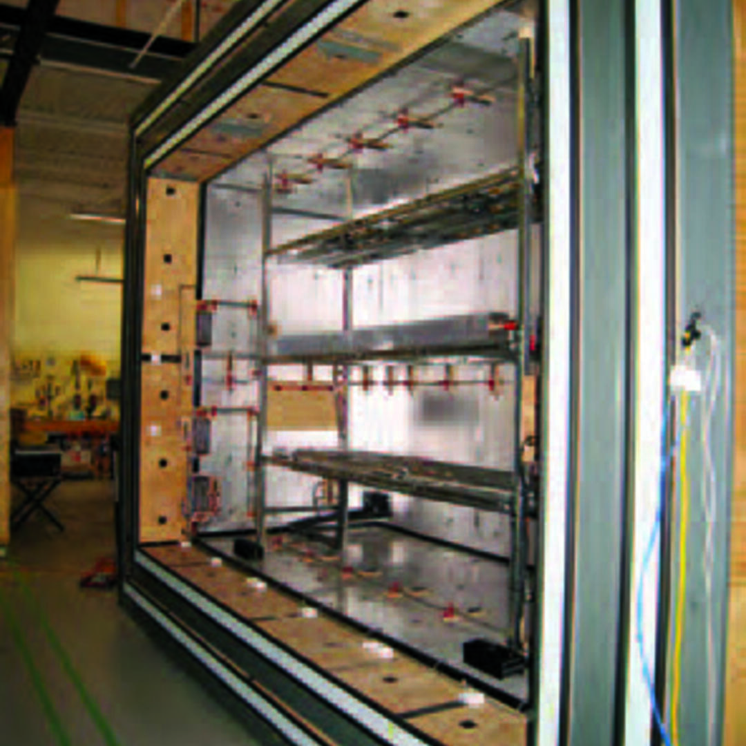
 | Hot-box Interior (Meter Box) Key improvements of the TM apparatus over other (i.e. conventional) hot boxes are:
|
Thermal bridging is a well understood and researched phenomenon, known to have a significant impact on the thermal performance of enclosure assemblies. This impact is beginning to be officially recognized by code authorities: for example, thermal bridging is incorporated into ASHRAE Standard 90.1 as well as the 2012 International Energy Conservation Code and the 2012 International Residential Code. Standard whole house energy modelling software often includes a framing factor, which accounts for a significant amount of thermal bridging. Commercially available heat transfer software, such as HEAT2, HEAT3 and THERM, can be used to assess the impact of thermal bridging in more complicated geometries. As the measurement and prediction of thermal bridging effects continues to improve, it will be more widely included in both energy models and building codes and standards. Our research contributes to this ongoing effort.
Temperature dependent thermal conductivity effects are less well-understood by the construction industry. Research conducted by manufacturers and independent researchers has established that insulation performs differently at different mean temperatures; however, this research is not common knowledge amongst designers, builders, code officials, or policy makers. As well, further research is required to assess the impact of temperature effects on annual energy usage. These data can be used to improve building codes and computer-based energy models, which do not currently account for the temperature dependency of insulation.
Other factors, such as air flow interactions, are just beginning to be researched in greater detail. Air flow is known to have a significant impact on building energy use. Typically, air leakage, such as infiltration or exfiltration, is the primary concern. However, when pressure differences are analyzed across an assembly, complexities occur involving flow paths and interactions between the air and the assembly components. These complexities need more research to understand their impact. Standard hot box methods (i.e. ASTM C1363) do not account for air flow interactions. The TM project was designed in part to address this limitation.
Experimental Design
During Phase I, a new hot-box apparatus and test method were developed to study the thermal performance of full-scale 8 ft x 12 ft wall assemblies exposed to realistic outdoor temperatures (-25 to 145°F, -32 to 63°C) and air pressures of ±25 Pa for flows up to 32 cfm, 900 lpm. The apparatus and test method account for the effects of thermal bridging, temperature dependency of insulation R-value, and interactions between heat flow and airflow. Moisture dependency and time dependency were specifically excluded (i.e. hot-box RH is maintained at 10-20% and wall specimens are seasoned prior to testing). Phase I concluded in 2010.
During Phase II, testing was completed on a series of wood-framed wall assemblies that were selected to represent common construction methods in regions throughout North America. Five wall assemblies were constructed to achieve a nominal insulation R-value of 13 (RSI 2.28), using 2x4 framing at 16 in (406 mm) on center. The following stud-space insulation materials have been tested:
- Damp-sprayed cellulose fiber insulation
- Inset-stapled kraft-faced fiberglass batt
- Face-stapled kraft-faced fiberglass batt
- Open-cell sprayed polyurethane foam
- Closed-cell sprayed polyurethane foam
Two additional assemblies were constructed to examine the impact of adding more insulation:
- 2x4 @ 16” (406 mm) o.c. with nominal R13 (RSI 2.28) friction-fit fiberglass batt + nominal R5 (RSI 0.88) 1” (25.4 mm) XPS exterior insulating sheathing
- 2x6 @ 16” (406 mm) o.c. with nominal R21 (RSI 3.70) friction-fit fiberglass batt
All of the assemblies had realistic but minimal thermal bridging (i.e. no extra framing beyond regularly spaced studs at 16 in (406 mm) on center, a double top plate, and single bottom plate, resulting in a 13.6% framing factor) and were more airtight than most real wall assemblies (e.g. 0.05 to 0.20 cfm50/ft2, 0.25 to 1.00 L/sm2@50Pa) .
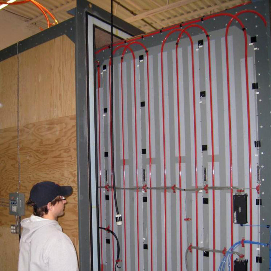
 | Double Guard on Meter Box An insulated guard box (left) minimizes the influence of temperature changes in the lab and reduces spatial temperature gradients over the meter box surface. A hydronic guard loop is installed over the outside surface of the meter box (right) to further reduce any spatial temperature gradients; it also all but eliminates any temperature difference between the inside and the outside of the meter box walls (minimizing if not eliminating heat flow through the five enclosing sides of the meter box). |
Who is Involved
Partners in the TM Consortium include:
- Dow
- GreenFiber
- Honeywell
- Huntsman Polyurethanes
- Icynene
- NAIMA (the North American Insulation Manufacturers Association)
Principal researchers from Building Science Corporation are:
Joseph Lstiburek, John Straube, Chris Schumacher, Aaron Grin, Robert Lepage.
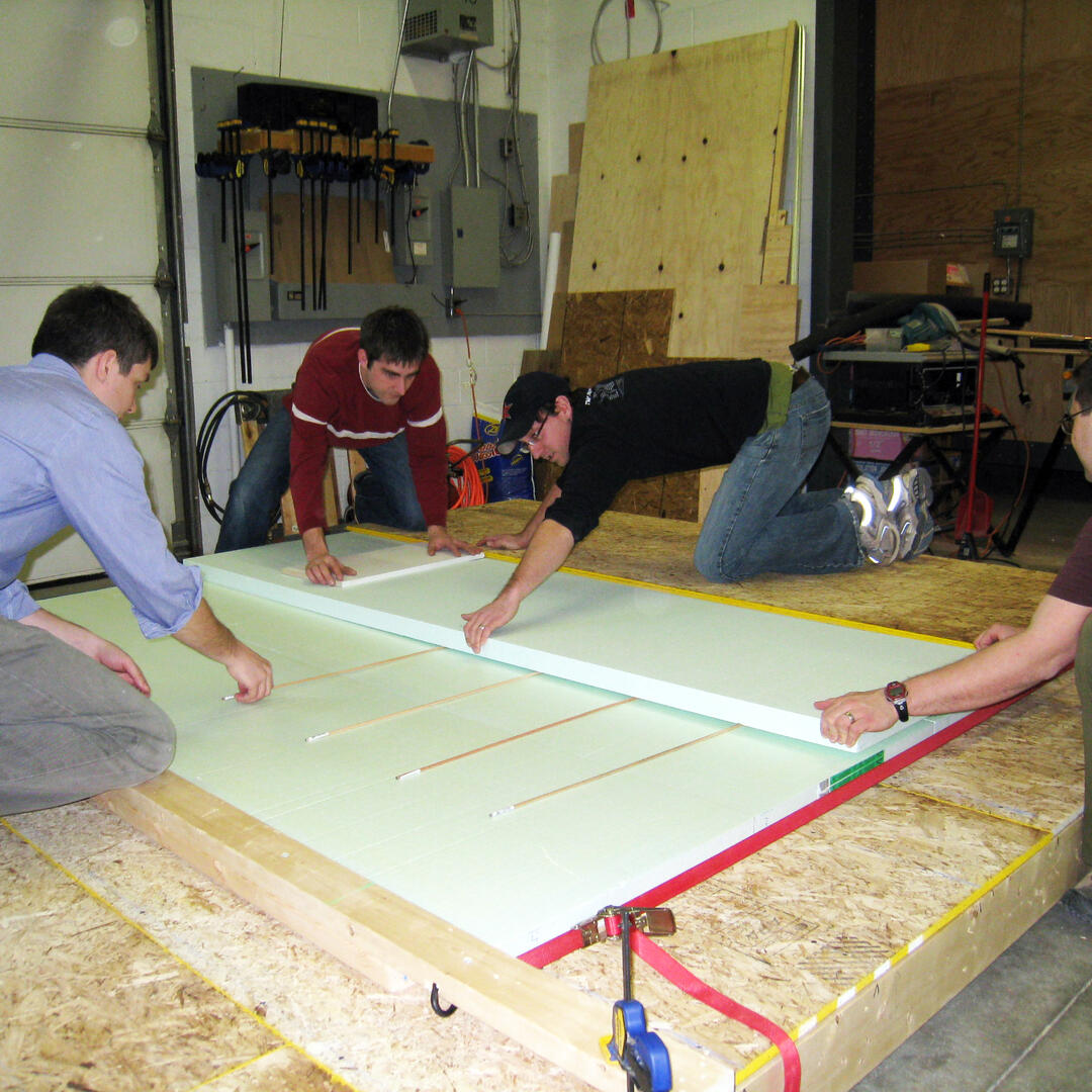
 | BSC Researchers Constructing Calibration Panels Commissioning and calibration were conducted by BSC for the measurement and control subsystems and for the complete TM hot box apparatus. Construction, commissioning, and calibration were completed between 2007 and 2009. A base set of walls was then tested to develop a set of reference values for future research. |
What We Have Learned/Demonstrated
A number of important points have been confirmed or identified during the first two phases of the TM project.
Thermal bridging can be measured and modeled.
Thermal bridging through the framing resulted in a roughly 15% decrease in thermal performance in all of the tested wall assemblies. Commercially available 2D and 3D heat transfer models provided good predictions of the thermal bridging in the test walls, as did the parallel path method described in the ASHRAE Handbook of Fundamentals and other texts.
R-values change with temperature.
All of the insulation materials tested to date exhibited temperature-dependent thermal performance. For the insulations used, the temperature-dependence effect resulted in improved thermal performance at lower temperatures (e.g. an outdoor temperature of 0°F, -18°C resulted in roughly a 10% improvement in thermal performance of the insulation) and reduced thermal performance at higher temperatures (e.g. an outdoor temperature of 144°F, 62°C resulted in roughly a 15% decrease in thermal performance of the insulation).
Air sealing is critical.
When walls are constructed with the same installed R-value in the stud space, and air sealed both inside and outside (i.e. there is zero air leakage through the assembly), they exhibit essentially the same thermal performance regardless of the type of insulation material used. When not properly air-sealed, any wall assembly will experience some loss in thermal performance due to air movement through the assembly. Not all systems are affected equally; the performance impact depends on the rate of airflow, the flow direction and the interaction between the air and the materials that comprise the assembly.
Air flow is complex and needs to be better understood.
The energy impact of airflow appears to be affected by the flow path and the interaction between the air and the materials in the assembly. Conventional models may over-predict the energy impact of air leakage through walls when there is a significant air flow interaction effect.
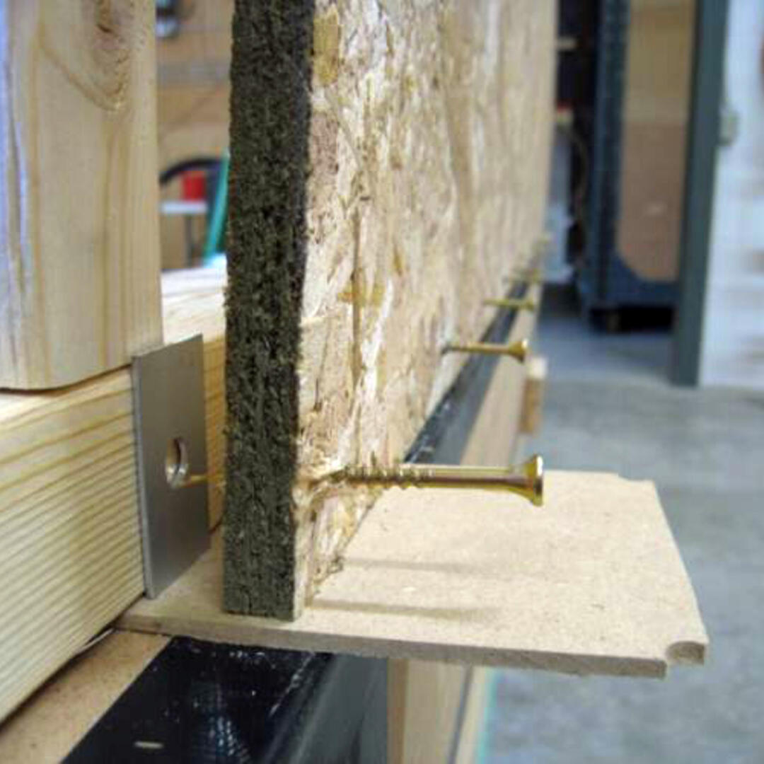
 | Spacer Installation In developing the test box method, a variety of spacers and spacer locations were compared in order to attain a representative and repeatable imposed gap for air leakage. The final design used 1/32 in (0.8 mm) spacers to create the imposed air leakage path between components of the assembly. |


