Project Team: Grifcon Contracting, Builder; Henry P. MacLean, Timeless Architecture, Architect and DER Lead; Building Science Corporation, DER Consultants and Technical Support; Drew Gillett, PE, Energy Consultant; PowerHouse Dynamics and Solar Wave Energy Inc., Energy Monitoring; National Grid, Massachusetts, DER Pilot Program Administrator/Sponsor
Location: Quincy, Massachusetts
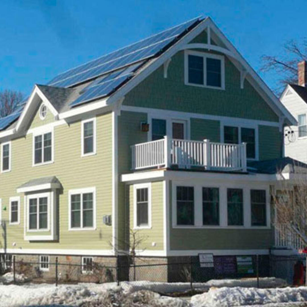
Description: Comprehensive renovation and expansion of circa 1905 bungalow
Completion Date: December 2010
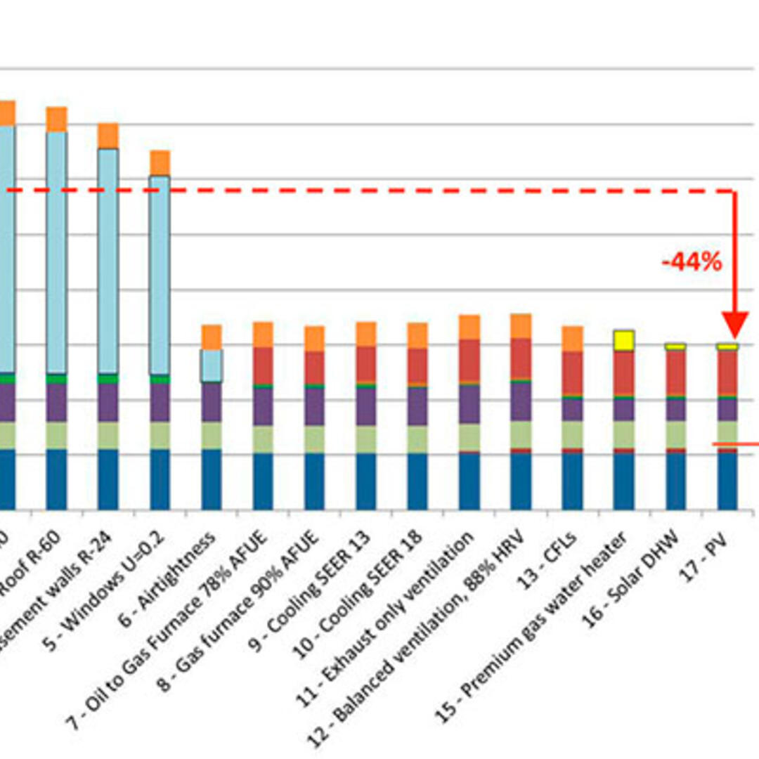
Estimated Annual Energy Savings: Source energy reduction is 66% with predicted PV generation (44% without PV); expected to meet Thousand Home Challenge
Overview
When the owners of this bungalow-style home in Quincy, Massachusetts originally decided on a major expansion, significant energy improvements were not part of their plan. The National Grid Deep Energy Retrofit (DER) pilot program brought the prospect of financial incentives and technical support. This helped the architect on the project, Henry MacLean of Timeless Architecture, to successfully make the case for pursuing a very high level of performance. The owners decided to pursue the DER to position the home to benefit from future energy savings while expanding available space for their five-person family.
During the DER process an additional floor was added to the home, as well as an entirely new roof with a 6.255 kW PV array.
The owners are pursuing Thousand Home Challenge designation through Affordable Comfort Inc. The building enclosure and mechanical systems offer a solid framework toward meeting the very ambitious energy use targets. The occupants will also use extensive energy monitoring to keep them on track toward low energy operation.
Design
The design includes significant reconfiguration to accommodate a growing family, pending move-in of an elderly parent, and careers performed from in-home offices–all within an existing foot print. The foundation walls and first floor enclosure structure were retained. The roof and half-story beneath the roof were demolished to make way for a new full 2nd floor plus half-story under a new roof.
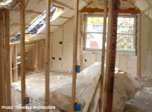
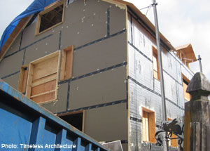
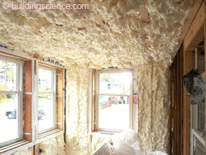
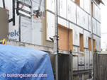
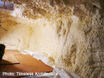
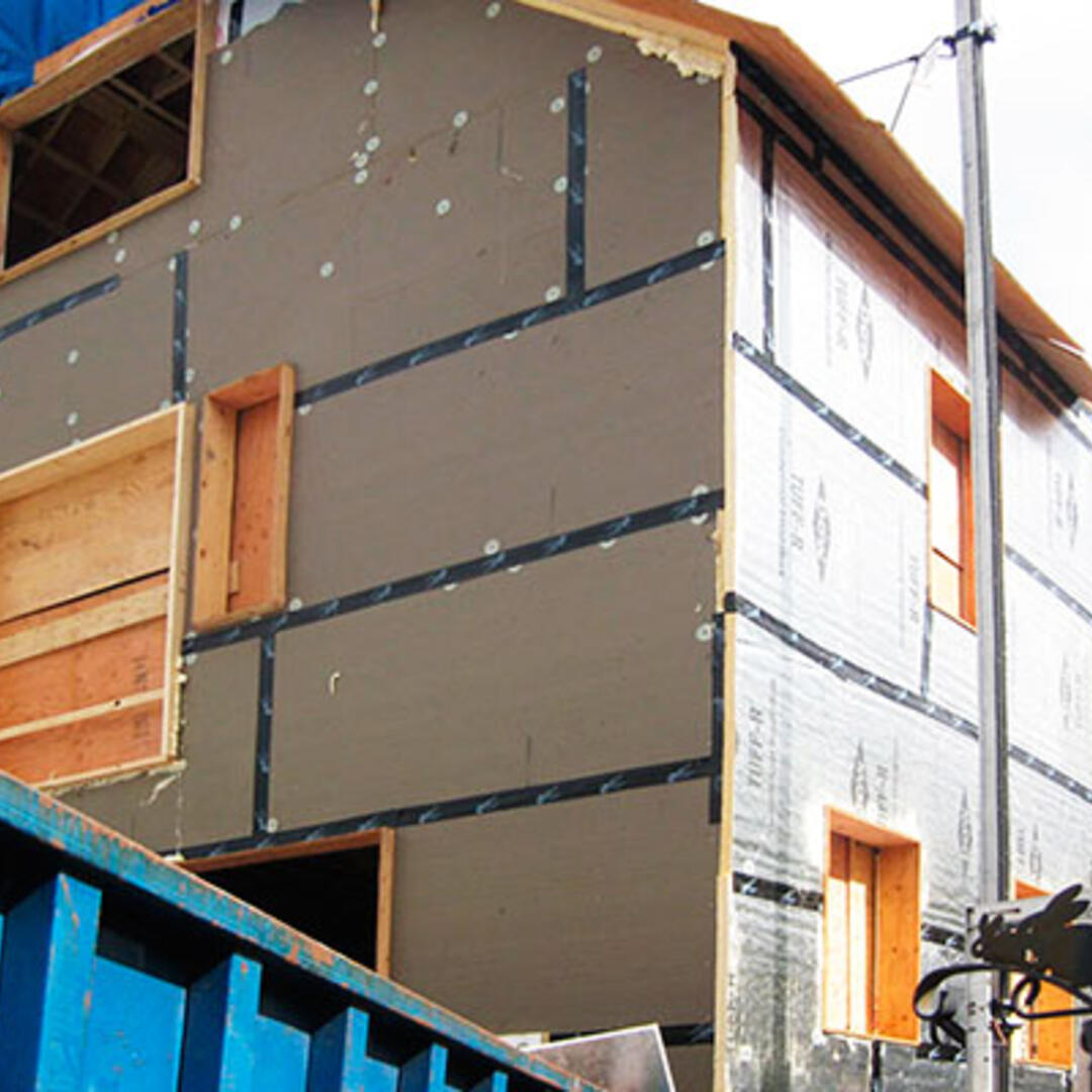
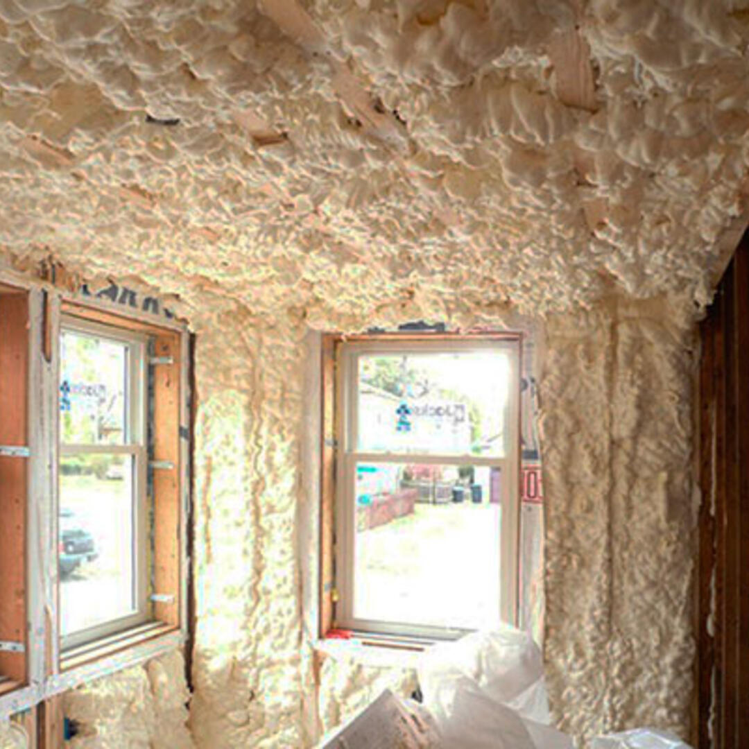
The architect designed the retrofit of the existing enclosure as well as the new structure to provide a high level of thermal performance. Roof eaves, rake extensions and, even, a false dormer detail, were attached over a continuous airflow control layer and exterior insulation. Other details were also designed to minimize thermal bridging. To complement the air flow control of a carefully detailed housewrap and 2 layers of exterior insulation, framing cavities in exterior wood-framed walls and roof are filled with open-cell spray foam. Closed-cell foam is applied to the framing sill and granite block foundation wall. The architect specified a high-density EPS foam board as a substitution for XPS beneath the radiant slab out of concern for the blowing agents used in XPS foam.
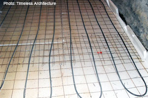
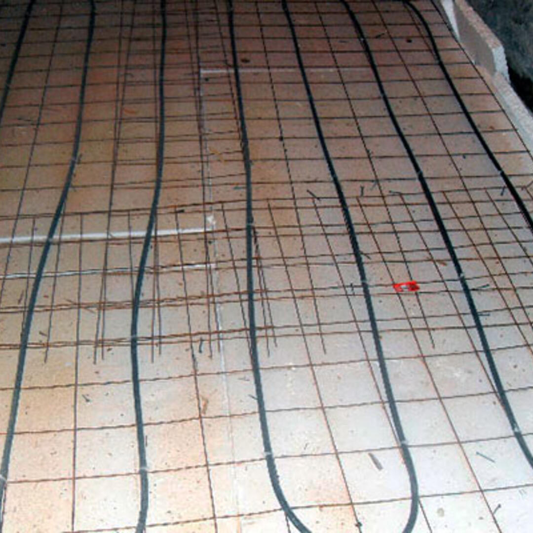
The heating system offers redundancy both in the delivery system and in the heat source. The primary heating distribution is through a central air handler with 3 ducted zones. A hydronic radiant distribution system was cast into the new basement slab. Panel radiators serve two of the rooms on the first floor.
The air handler is designed for dual-fuel heating with a refrigerant coil served by a high efficiency air-source heat pump and a hot water coil served by a heat-exchanger loop to a high efficiency direct-fired storage water heater. The storage water heater is also connected to a solar thermal panel array. During design, the importance of a separate thermal storage tank for the solar thermal system was discussed. In the end, space constraints dictated a single combined storage and finishing tank.
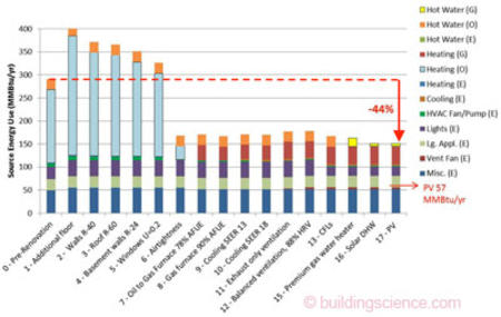
Parametric Study of Source Energy Use
(Image from BSC generated by NREL’s BEOpt 1.1 for retrofits)
Enclosure Design
Roof Assembly: R-62 unvented roof: 10” Icynene® open-cell spray foam insulation in rafter cavities; roof sheathing; housewrap; two layers of 2” polyisocyanurate insulating sheathing, joints offset and taped; plywood nail base; roof underlayment; asphalt shingles.
Wall Assembly: R-38 (nominal): Icynene® open-cell spray foam insulation in 2x4 wall framing cavities; existing board sheathing or new plywood sheathing; housewrap; two layers of 2” polyisocyanurate insulating sheathing joints offset and taped; 1x3 wood furring; fiber cement siding.
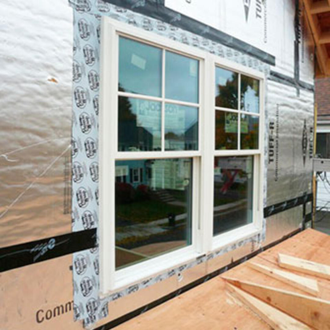
Window Specifications: New Paradigm triple-pane, vinyl framed, low-e, krypton blend or argon gas filled; U=0.20 – 0.26, SHGC=0.23 – 0.21; windows installed in plane with primary water control layer.
Air Sealing: Taped housewrap over roof and wall sheathing; adhered membrane wrapping from roof to wall; two layers of 2” polyisocyanurate insulating sheathing joints offset and taped; open-cell spray foam insulation in wall and roof framing cavities; closed-cell spray foam applied over framing sill and granite block foundation wall; spray foam extends to new concrete slab.
Foundation Assembly: Conditioned basement: 2” closed-cell spray foam applied over framing sill and foundation wall; 3½” fiberglass batt in new wall framing cavity; 6-10” gravel, 2½” EPS insulation; polyethylene vapor retarder under new concrete slab with radiant tubing.
Construction
Excellent collaboration between the architect, general contractor and framing/siding subcontractor contributed to success in implementing unfamiliar details.
Members of the construction crew demonstrated an enthusiasm for the goals of airtightness and insulation continuity. This enthusiasm was matched with an understanding of how to achieve airtightness and thermal barrier continuity through the many stages of construction.
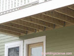
Changes to the design implemented during construction for performance reasons include additional support for the outdoor deck. This avoided thermal bridging of structural connections to the house. An access was also cut into the front room/porch floor to provide access to better insulate the crawlspace below.
The expanded polystyrene (EPS) insulation specified to insulate the new basement slab proved difficult to source and not rugged enough to stand up to the conditions of the construction site.
Mechanical Design
Heating and Cooling: Carrier Infinity® two stage heat pump; SEER 16.5; HSPF 9.5; Phoenix Evolution Versa-Hydro™ direct-fired storage water heater with heat exchanger for heating and for input from solar thermal system.
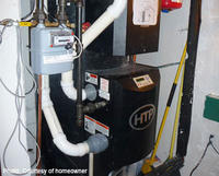
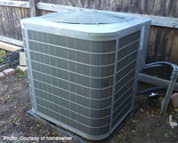
Water heater (left) and heat pump (right)
Ventilation: LifeBreath HRV, ducted to central AHU distribution.
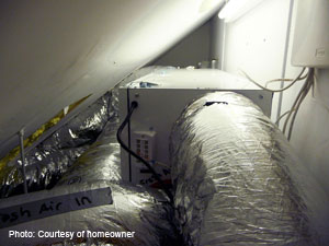
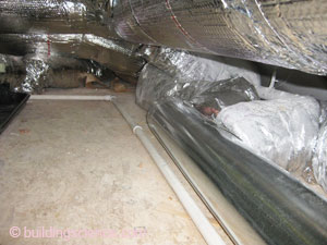
Heat recovery ventilator (HRV) ducts
Space Conditioning Distribution: Ductwork for forced-air system entirely within conditioned space; hydronic radiant in new concrete basement slab; hydronic panel radiator at entry and front/porch room.
DHW: Phoenix Evolution Versa-Hydro™ direct-fired storage water heater with heat exchanger for input from 6 Velux integrated solar thermal collector panels.
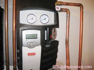
Input from Velux solar thermal panels
Lighting: ENERGY STAR® CFL lighting.
Appliances: ENERGY STAR® dishwasher, refrigerator and clothes washer.
Site Generated Power: 6.25 kW solar PV array.
Testing and On-Site Technical Support
Early in the project cycle, BSC assisted the architect in communicating performance goals to the HVAC subcontractors at on-site meetings. During the course of construction BSC conducted multiple site visits to review construction details with the architect and general contractor. During one such visit, BSC guided the general contractor and framing/siding subcontractor through a mock up window installation.
BSC performed both pre- and post-retrofit air leakage testing to assess the air leakage reduction. The pre-retrofit air leakage measurement was 5050 cfm at 50 Pascals or 18.5 ACH50 and the post-retrofit measure was 762 cfm50 or 1.26 ACH50. Despite a significant increase in the enclosure surface area, the project achieved huge reduction in measured air leakage.
During measurement and verification testing, BSC noted that the HRV was ducted to the central forced-air system in a way that would allow air to be drawn through the ventilation unit when the ventilation system is not running. BSC performed duct leakage diagnostics to estimate the magnitude of this unintended ventilation so that the programmed ventilation rate could be adjusted accordingly.
Moving Forward
The extensive energy monitoring commissioned by the owners and architect to guide operation of the home creates a unique opportunity to gauge the performance of complex systems. The project team has maintained an agreement to share data with BSC and the DER Pilot Program sponsor, thus providing further opportunity to learn from this project.
Design Challenge: Mock-Up Makes Perfect This project represented the first implementation of thick exterior insulation (>2”) for both the general contractor and the framing/siding subcontractor. During an early construction-phase site visit, BSC guided the general contractor and framing/siding subcontractor through a mock-up window installation. This exercise helped both contractors to develop a level of comfort and confidence in the designed window installation details. This was particularly important as the window placement needed for proper water management and airflow control requires a deviation from standard practice. Subsequently, the project construction team constructed a wall section mock-up that demonstrated window flashing, air sealing, and attachment of exterior insulation. Both mock-ups provided opportunities to resolve unique installation questions and also proved effective communication tools. |

