The Thermal Metric Hot Box Apparatus
For the purposes of the Thermal Metric (TM) research project a novel double-guarded hot box apparatus was designed and constructed (Figure 1). The apparatus is based as closely as possible on ASTM C1363 (the accepted standard for conventional hot boxes). However, a number of improvements have been made to facilitate the research. These include:
- A deeper meter box to permit the testing of wall-to-wall and wall-to-floor intersections at full scale
- Carefully controlled and metered equipment to both heat and cool the meter box
- Draw-through fans to create more realistic airflow over the indoor surface of the wall specimen
- A double guard (insulated guard box + liquid guard loop) to improve spatial and temporal control over the temperature differential across the meter box walls and minimize uncertainties
- A modified and calibrated specimen frame, or ‘cartridge’, to control flow of heat and mass at the perimeter of the metered area of the test wall specimen
- A carefully controlled and metered air transfer system to induce infiltration or exfiltration and measure the energy associated with airflow
General Construction Details
The walls of the TM hot box are custom-assembled structural insulated panels (SIPs) comprising 7/16 in (11 mm) plywood adhered to either side of a solid layer of 4 in (100 mm) XPS insulation. These SIPs are attached to the inside of a steel exoskeleton using fasteners that only penetrate the outer layer of plywood. The SIPs panels are fabricated inside the exoskeleton so panel joints only occur at corners. This creates a stiff, strong, airtight wall with continuous thermal resistance of more than R21 (RSI 3.7).
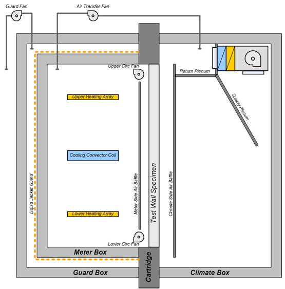
Figure 1: Schematic of thermal metric research hot box apparatus
Meter Box
|
The space conditioning system used in the meter box employs hydronic cooling and electric resistance heating. The meter box cooling is measured using high precision RTDs in combination with a precision flow meter to accurately quantify the heat removed from (or cooling provided to) the meter box. Heat is added to the meter box via PID-controlled electric heaters. Precision resistor circuits are employed to measure the heat added to the meter box. By balancing the system’s heating and cooling, a constant and precise temperature can be maintained and the total heat addition/removal can be measured. The inside surfaces of the meter box are insulated with an additional R10 (RSI 1.76) of foil-faced insulation to bring the total meter box R-value to over R31 (RSI 5.46). An insulated baffle separates the airspace (i.e. next to the indoor side of the test wall specimen) from the mixing chamber of the meter box (i.e. the portion where heat is added/removed). The baffle panels are constructed using 3/4 in (19 mm) foil-faced polyiso insulation. The foil face is exposed on the mixing chamber side (to limit radiant heat transfer between the electric resistance heaters/cooling coil and the baffle). |
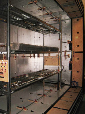
Figure 2: Upper and lower heating arrays with cooling coil in meter box |
The foil skin and the thermal resistance of the baffle panels ensures that the wall-side of the baffle is at a (spatially and temporally) constant temperature that is close to that of the air in the baffle space (i.e. the air traveling across the face of the test wall specimen).
The wall-side of the baffle panel is painted flat black to ensure that the surface of the test wall specimen radiates to the baffle as a real wall would to its surrounding environment. Calibrated precision thermistors +/-0.2°F (+/-0.1°C) are used to measure temperatures at 24 points on the baffle surface, 24 corresponding points in the air stream and at least 24 points on the interior surface of the test specimen.
Air is drawn through the meter box baffle space at velocities representative of natural convection in real world conditions, typically around 1fps (0.3 m/s). DC powered axial draw-through circulation fans, at the top and bottom of the baffle, are used to ensure smooth flow along the surface of the wall sample in the direction that natural convection would occur. In hot climate tests, the top fans draw air out from the top of the baffle, pulling room temperature air into the bottom of the baffle space, whereas during cold climate tests, the bottom fans draw air out of the bottom of the baffle space, pulling room temperature air into the top of the baffle space. In short, the fans are used to replicate the natural convection that occurs in real rooms, suppressing heater-driven convective looping and eddies that could influence the test
When not properly air-sealed, any wall assembly will experience some loss in thermal performance due to air movement through the assembly. Not all systems are affected equally; the performance impact depends on the rate of airflow, the flow direction and the interaction between the air and the materials that comprise the assembly.
Double Guard
The TM hot box employs a calibrated, double guarded hot box strategy: an insulated guard box surrounds the meter box and a hydronic guard loop is installed over the outside surface of the meter box, as seen in Figure 3. The guard box minimizes the influence of temperature changes in the laboratory and helps ensure a (temporally) constant temperature around the meter box. The liquid guard loop further ensures the outside surface of the meter box remains at a (spatially) constant temperature and all but eliminates any temperature difference between the inside and outside of the meter box. This strategy all but eliminates any energy flow across the meter box walls.
Temperature differences across the meter box walls are measured by paired precision thermistor arrays that are applied to the inside & outside of each of the five faces of the meter box at a total of 176 locations. The hot box control system adjusts the temperature of the liquid guard loop to reduce the average temperature difference to less than 0.09°F (0.05°C).
The temperature difference is measured by paired precision thermistor arrays that are applied to the inside and outside of each of the five faces of the meter chamber at a total of 176 locations. The hot box control system reduces the average temperature difference across the meter box walls to less than 0.09°F (0.05°C).
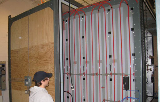
Figure 3: Double guard: guard box (left) and liquid guard loop on meter box (right)
Climate Box
The climate box has the same dimensions and construction as the guard box. The climate side air baffles are constructed using the same materials and methods as the air baffles in the meter box. Foil-faced polyisocyanurate insulation is also used to form the supply and return plenums. The supply plenum runs halfway down the back wall and is terminated with air flow vanes to minimize turbulence from the fan coils and tune airflow into the bottom of the baffle space. Four fan coil units draw air out of the baffle space and into the return plenum to minimize turbulence across the wall surface.
Heat is added to/removed from the climate box via the four fan coils which are connected to an air-cooled liquid chiller and a hydronic heater. An array of pulse-controlled electric resistance heaters permits fine tuning of the temperatures and ensures that temperatures remain within +/- 0.09°F (0.05°C) of the set point for the duration of the test.
One of the primary features of the climate box is the capacity to run a range of realistic outdoor temperatures, from -18°F (-28°C) up to 144°F (62°C). This enables the wall assembly to remain undisturbed when tested from very cold to very hot climatic conditions. Conventional hot boxes only measure heating in the meter box so it is necessary for technicians to remove, reverse, and reinstall the wall sample to switch between hot or cold tests.
Wall Cartridge
In a conventional guarded hot box, the wall test specimen area extends beyond the perimeter of the meter box. The portion of the wall that is between the meter box and the climate box experiences the same heat flow as the portion that is between the guard box and the climate box so there is no heat flow in the plane of the test wall. This is an extremely effective method of minimizing flanking losses; however, when hollow (e.g. framed) walls are tested, it provides several paths for air to flow. The interaction between heat and airflow is of particular interest in the Thermal Metric research program, hence the team felt it necessary to design a specimen frame that would not only minimize flanking losses, but also eliminate airflow outside of the area of the wall test specimen.
The TM hot box specimen frame or ‘cartridge’ is made of alternating layers of 7/16 in (11 mm) plywood and 4 in (100 mm) XPS foam board laminated to create an exceptionally stiff, extremely well insulated sandwich panel, as seen in Figure 4. Two 2 x 2 in (38 x 38 mm) nailers are embedded in the cartridge to provide fastening support. A 4 in (100 mm) thick polyisocyanurate thermal break lines the entire rough opening of the cartridge so that the finished opening and the size of the wall test specimen match the meter box opening: 12 ft wide by 8 ft high (3.66m x 2.44m).
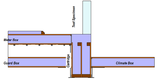
Figure 4: Section through wall cartridge with meter, guard and climate boxes in position
The wall test specimen is positioned so that its cladding is in plane with the climate side of the wall cartridge. The geometry allows space for air in the climate box to turn the corner and achieve spatial uniformity before it passes over the surface of the wall test specimen. This is important when considering the interaction between heat flow and airflow. The arrangement does, however, complicate the flanking loss, because there is a portion of the cartridge that is exposed to the meter box but is not guarded (i.e. that portion of the thermal break that lies between the inside face of the drywall and the meter box gasket). Steady state two-dimensional heat flow analysis was conducted using HEAT2 to optimize the wall cartridge design. Calibration tests were conducted to measure actual flanking losses at each testing temperature to levels superior to those in industry-standard heat boxes.
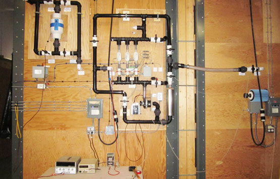
Air Transfer System
The air transfer system (ATS), pictured in Figure 5, generates a pressure difference between the meter box and the climate box to drive airflow through available paths in the test wall specimen. It can be used to negatively pressurize (i.e. induce infiltration) or positively pressurize (i.e. induce exfiltration) the meter box. A variable speed DC guard fan is used to minimize the pressure difference between meter and guard boxes so that airflow only occurs between the meter and the climate boxes. The air flow is measured using three high precision mass flow sensors. Typically, air flows are small enough that a single mass flow sensor is sufficient. However, leakier walls require a greater amount of air flow to maintain a pressure. In these instances, all three mass flow sensors are used.
Two versions of each wall were tested: an as-built wall, and a sealed version of the wall. The as-built walls incorporate intentional, realistic, repeatable gaps and leakage paths within the wall. The sealed walls are sealed on both sides with polyethylene sheeting. Each of these wall types is discussed in more detail in Thermal Metric Test Wall Construction and Installation.
A tracer gas system (using CO2 and monitors within the meter box, guard box, climate box, and laboratory) is also used to continuously monitor the air flow through the assembly at every test point. Good agreement between the CO2 tracer gas system and the ATS is regularly achieved.