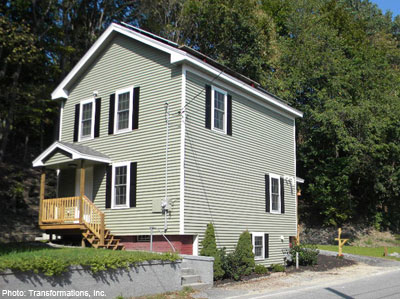
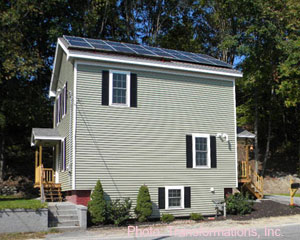
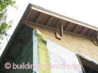
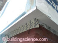
Habitat for Humanity North Central Massachusetts received this circa 1900 property as a donation from the Town of Lancaster. The building had been in a state of significant deterioration, yet preserving the footprint and first floor framing was essential to preserving the ability of Habitat to provide a home on the otherwise non-conforming lot. Due to programmatic requirements, the roof was removed and a new second floor and roof framed on top of the existing balloon-framed structure. Significant parts of the rubble-stone-and-brick foundation wall also required replacement. The interior of the remaining first floor was completely gutted.
Being a Habitat project, the project plan needed to be formed around donated materials and volunteer labor. The result is a project that serves as an impressive example of what is attainable under such circumstances. The project also developed interesting strategies to pursue ambitious performance targets with the available materials and resources.
In addition to the super-insulated enclosure, triple-glazed windows, energy-efficient mechanical systems and exceptional airtightness, the house design also includes a 3.75 kW PV array. The completed house was turned over to the new homeowners in August of 2011.
Project Team: Habitat for Humanity North Central Massachusetts, Builder; Transformations, Inc., DER Lead and architectural design support; Building Science Corporation, Consultants and DER Technical Support; National Grid, Massachusetts, DER Pilot Program Administrator/Sponsor
Location: Lancaster, Massachusetts
Description: 1,440 ft2 two bedroom, one bathroom, 2 stories plus partial basement single family Colonial
Completion Date: August 2011
Estimated Annual Energy Savings: Projected 50% energy use reduction compared to pre-retrofit conditions
Design
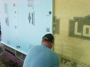
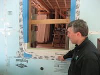
In order to achieve the thermal performance targets set by the National Grid Deep Energy Retrofit pilot program the project decided to use closed-cell spray foam in the wall cavities in addition to donated 4” of XPS rigid foam insulation on the exterior. However, since both types of insulation are vapor impermeable BSC expressed concern for the durability of the wall assembly and offered solutions to provide better moisture management. The Habitat Construction Manager elected to install a breather mesh over the wood sheathing between a housewrap and the first layer of exterior insulation. This allows for the assembly to redistribute and dissipate moisture if small amounts of water get behind the primary drainage plane, the rigid foam.
Water control at the roof is provided by standard roofing practices. Purpose-built roof trusses enable adequate overhangs while the new rakes are extended to provide ample protection for the walls below. The wall system uses the exterior face of the insulating sheathing as the primary drainage plane with the housewrap layer behind the vapor diffusion mesh as a secondary drainage plane. A new exterior footing drain at the rear (uphill side) and a layer of gravel beneath the new basement slab are designed provide water control for the foundation.
Air flow control at the top of the building is achieved by sealing the perimeter and sealing penetrations at the top floor ceiling. Careful detailing is needed to transition the ceiling air flow control to that of the wall system. A raised heel truss allows the full depth of insulation to continue to the perimeter of the attic. Rigid foam installed up the height of the raised heel protects the ceiling insulation from windwashing or displacement. This approach accommodates very high levels of insulation at a low marginal cost. Mechanical systems and ventilation distribution are located entirely within the conditioned space and not in the vented attic.
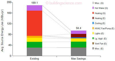
Modeled Source Energy Savings
(Image from BSC generated by NREL’s BEOpt 1.1 for retrofits)
Enclosure Design
Roof Assembly: R-65 vented attic; 1” closed-cell spray foam on attic floor covered with 18” loose-blown cellulose.
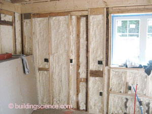
Wall Assembly: R-44 (nominal); existing 2x4 and new 2x6 wall cavities filled with closed-cell spray foam; housewrap; breather mesh; two layers of 2” XPS insulating sheathing; 3/4” furring strips; vinyl siding.
Window Specifications: Paradigm triple-glazed, krypton/argon blend, low-E vinyl windows; U=0.2, SHGC=0.23; windows installed over strapping at exterior face of insulating sheathing.
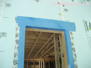
Air Sealing: Taped housewrap over existing board- and new OSB sheathing; closed-cell spray foam in wall framing cavities and calking at framing joints; 1” closed-cell spray foam flash coat at attic floor; housewrap wraps over the top plate of second floor wall where closed-cell spray foam on attic floor extends over the top plate and connects to housewrap; the bottom of the housewrap is sealed to the existing board sheathing and top of foundation wall; closed-cell spray foam at foundation wall extends and seals to the new concrete slab.
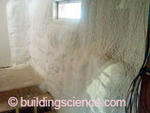
Foundation Assembly: Conditioned basement with minimum 3” closed-cell spray foam insulation applied directly to fieldstone and brick foundation walls and to new concrete wall in rear of building; dampproofing with 2” XPS insulating sheathing below grade at exterior of new concrete foundation wall; new concrete slab cast over sand layer, polyethylene vapor barrier, 2” XPS insulation and gravel.*
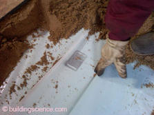
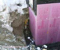
Foundation Assembly
* BSC does not recommend installing a sand layer under new slabs.
Construction
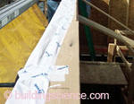
To address the challenge of connecting the air flow control layer of the wall system to that of the top floor ceiling, BSC advised the project team to wrap the wall housewrap onto the top plate and tape it to the top plate of the top floor wall prior to placement of the roof trusses. There was some concern that the placement of the roof trusses would tear the housewrap all to shreds. It appears that the housewrap has held up just fine.
The new basement slab was cast directly against the foundation wall which creates a thermal bridge and precluded establishing a direct connection between the water control function of the foundation wall with the sub-slab drainage system. What allows this system to still provide adequate control of liquid water is the exterior perimeter drain controlling ground water and the surface regarding which will improve draining of surface water away from the foundation.
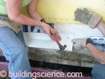
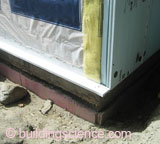
The project team used a brake-formed metal guard to protect the base of the foam wall from animals. Attachment of the guard to furring strips provides a reliable slope to the outside and the simple building footprint avoid inside corners where such a flashing element along the bottom of the wall might concentrate water.
Mechanical Design
Heating and Cooling: Mitsubishi Mr. Slim ductless minisplit air source heat pumps, one per floor..
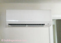
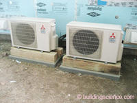
Ductless minisplit (left) and outdoor condensing units (right)
Ventilation: Ducted LifeBreath Heat Recovery Ventilator (HRV) located in the basement. Ventilation supply ducted to bedrooms, stale air exhausted from bathroom and kitchen.
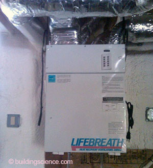
Heat recovery ventilator (HRV)
Space Conditioning Distribution: Ductless indoor section for air source heat pumps. HRV ducts inside the conditioned space with ducting configuration to provide some air mixing.
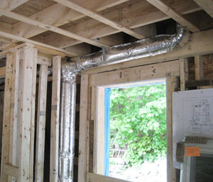
HRV ducts in conditioned space
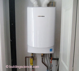
DHW: 0.98 EF Navien gas condensing tankless water heater.
Lighting: All CFLs in light fixtures.
Appliances: ENERGY STAR® dishwasher, refrigerator and clothes washer.
Site Generated Power: 3.75 kW PV system
Testing and On-Site Technical Support
Prior to the start of construction, leaders of the Habitat crew participated in a mock-up window installation led by BSC. BSC conducted site visits to review construction details with the builder, point out errors to repair in flashing or other elements, and to identify viable simplifications to the project. During one such site visit, BSC noted a ventilation duct passing through the attic space and worked with the builder to identify a different routing for the duct. The duct routing was subsequently changed to maintain the duct in condition space.
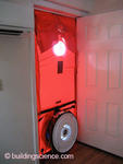
Since the property was in significant disrepair prior to the retrofit, pre-retrofit values for air leakage were based on measurements obtained for a neighboring building of similar configuration. The number measured was 33 ACH 50. During the post-retrofit testing of the Habitat DER, BSC guided volunteers to identify and seal air leaks around the house in order to meet the airtightness goal set by the National Grid DER pilot program. The final measurement came in at 1.6 ACH 50!
BSC conducted three site visits for this project to discuss various elements of the building. Installation of the windows, proper flashing, connections of the air and water control layers were discussed with the builder and the crew while on site.
Moving Forward
Monthly gas and electric bills will be collected from the homeowner to gauge performance of retrofit strategies employed.
BSC hopes to continue working with Habitat for Humanity of North Central Massachusetts in designing and building high performance affordable homes.
Design Highlight: Vapor Impermeable Wall Assembly This particular project employed an approach of combining 4” of exterior insulation and closed-cell SPF framing cavity insulation. The exterior foam insulation in this case is extruded polystyrene (XPS). The insulation in this assembly offers very low vapor permeability (i.e. low drying potential) to either side of the structure. This is a particular concern for a project where critical details may be implemented by unskilled volunteer labor. As a mitigation for the moisture risk a breather mesh was installed over the structural sheathing between the housewrap and the exterior rigid insulation boards. The breather mesh serves as a hygric redistribution layer to allow minor moisture concentrations to dissipate. While liquid water is able to drain over the housewrap and through the mesh layer, the mesh layer suppresses convection airflow sufficiently to avoid degradation of the thermal insulation to the exterior. |

