Wall assembly design and construction needs to consider rain, temperature, humidity as defined by the hygro-thermal regions, annual rainfall and the interior climate classes as environmental loads that affect mold, decay and corrosion as well as other degradation mechanisms. Design and construction needs to consider the exterior and interior environmental loads, the nature of the materials that comprise the environmental separation and the energy flow across the environmental separation.
Wall assemblies should be designed and constructed for specific hygro-thermal regions (Figure 1), rain exposure zones (Figure 2) and interior climate classes (Table 1). To this end the wall assembly should have four principal control layers or control approaches as overlays to the structure.
They are presented in order of importance:
- A water control layer or water control approach for rainwater
- An air control layer or air control approach for air transported moisture
- A vapor control layer or vapor control approach for vapor transported moisture
- A thermal control layer or thermal control approach for thermal transfer
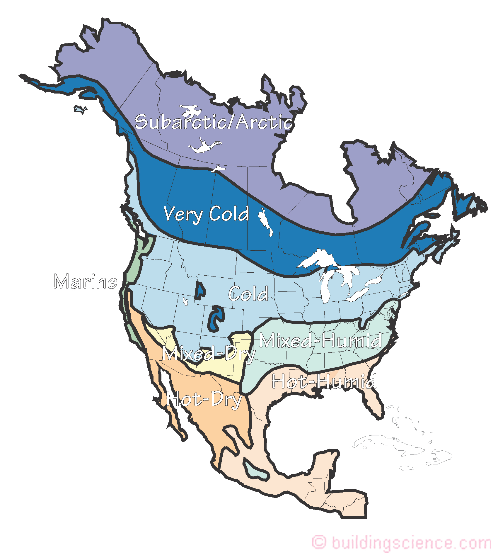
Figure 1: Hygrothermal Regions – Based on Herbertson’s Thermal Regions and Koeppen climate types (Lstiburek, J.W.; Environmental Loads, Eight Canadian Building Science Technology Conference, CSCE, February 2000 – adapted by PNNL to become the IECC Climate Zone Map and subsequently the ASHRAE Climate Zone Map).
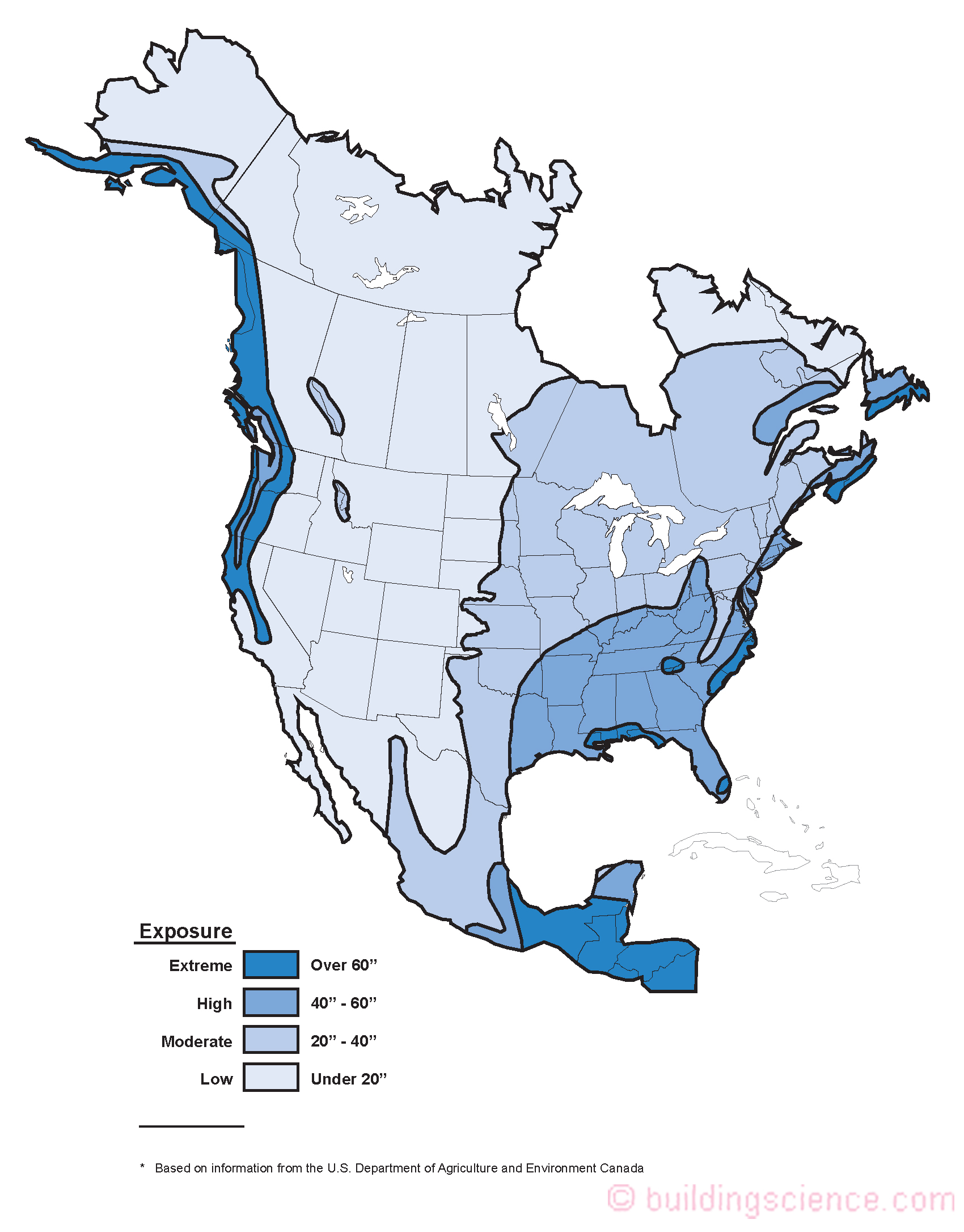
Figure 2: Rain Exposure Zones – Based on annual precipitation from the U.S. Department of Agriculture and Environment Canada (Lstiburek, J.W.; Environmental Loads, Eight Canadian Building Science Technology Conference, CSCE, February 2000).
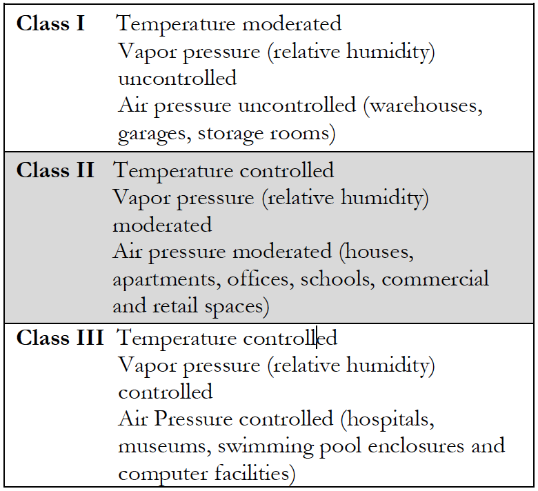
Table 1: Interior Climate Classes (Lstiburek, J.W.; Environmental Loads, Eight Canadian Building Science Technology Conference, CSCE, February 2000).
If a control layer approach is selected the best place for the control layers is to locate them on the outside of the structure in order to protect the structure. The optimum configuration is presented in Figure 3. However, many configurations are possible. In many assemblies a combination of control layers and control approaches are typical.
The most common examples of configurations of control layers and control approaches follow for wood frame and concrete masonry unit (CMU) assemblies. The configurations cite various classes of vapor control layers (Table 2) and the thermal resistance of exterior insulation to avoid condensation (Table 3).
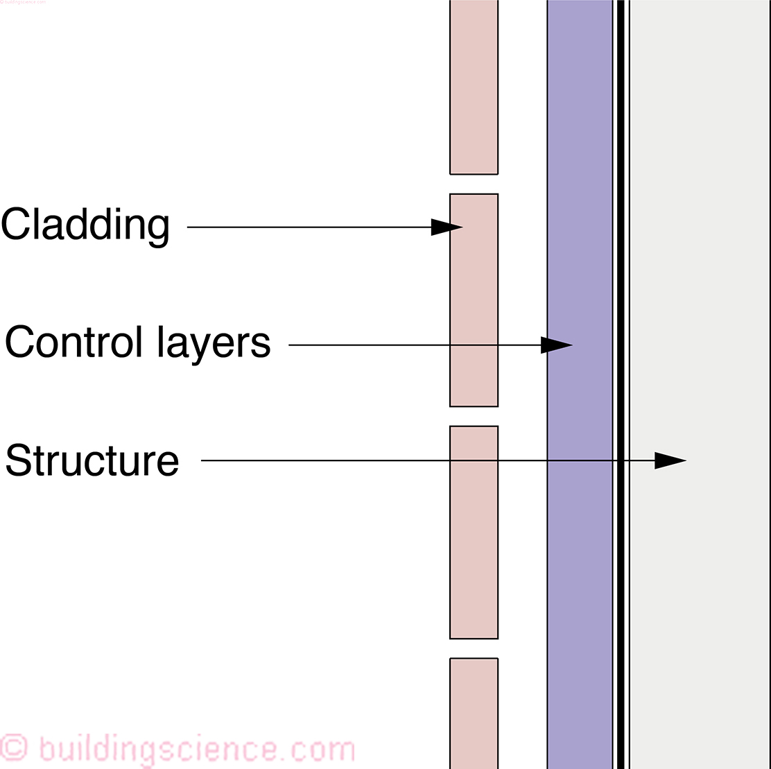
Figure 3: Control Layers – Optimum configuration is to place the control layers on the outside of the structure. (“The Perfect Wall”, ASHRAE Journal, May 2007).
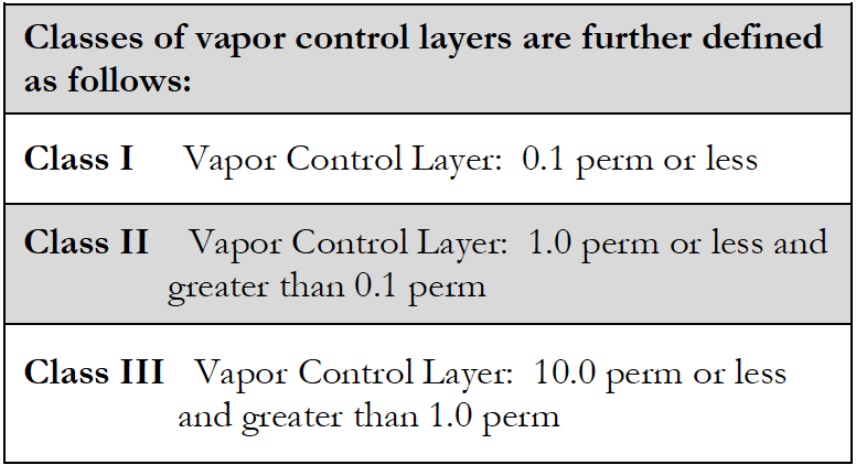
Table 2: (Lstiburek, J.W.; Understanding Vapor Barriers, ASHRAE Journal, August, 2004).
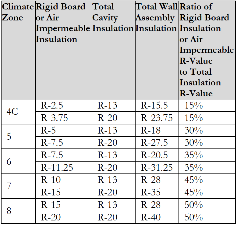
Table 3: Insulation for condensation control. (Adapted from Table R 702.1 2015 International Residential Code).
----------------------------------------------------------------------------------------------
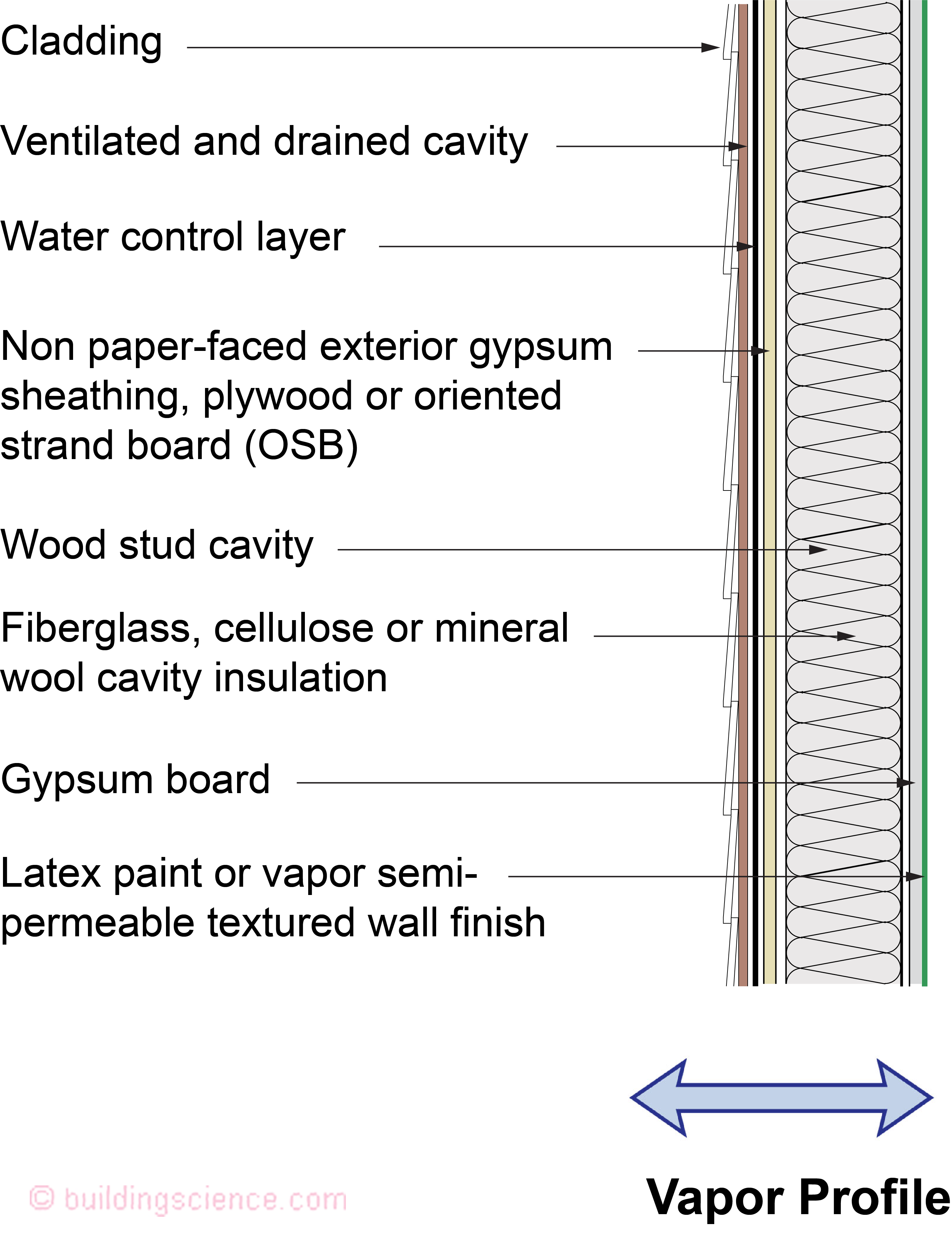
Figure 4: Wood Frame Assembly With Interior Cavity Insulation and Siding
Applicability
OK: hot-dry, hot-humid, mixed-dry, mixed-humid, marine, and cold regions.
NO: Very cold and subarctic/arctic regions.
NO: Interior climate class III buildings such as hospitals, museums, and swimming pool enclosures.
Description This wall is a flow through assembly: it can dry to both the exterior and the interior.
Drainage cavity The exterior siding should be uncoupled from the wall assembly with a ventilated and drained cavity. The air gap behind the cladding can be provided by using a textured housewrap, a drainage mat, or furring strips at least 3/16 inch thick.
Water control layer Mechanically fastened membrane (building paper or building wrap), vapor-permeable self-adhered membrane, fluid-applied membrane, or integral surface of the sheathing with taped joints
Air control layer Interior gypsum board, exterior gypsum board/structural sheathing, or exterior building wrap (water control layer)
Vapor control layer No specific vapor control layer. Controls vapor flow by allowing vapor transfer in both directions. Interior vapor control Class III latex paint on interior gypsum board.
Thermal control layer Stud bay cavity insulation
----------------------------------------------------------------------------------------------
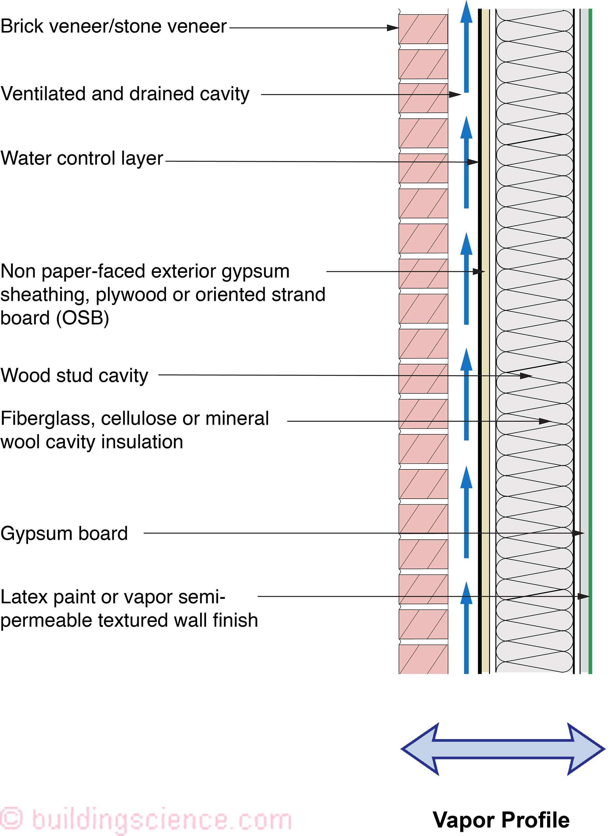
Figure 5: Wood Frame Assembly With Interior Cavity Insulation and Brick or Stone Veneer
Applicability
OK: hot-dry, hot-humid, mixed-dry, mixed-humid, marine, and cold regions
NO: Very cold and subarctic/arctic regions
NO: Interior climate class III buildings such as hospitals, museums, and swimming pool enclosures.
Description This wall is a variation of Figure 4. As in Figure 4, this wall is a flow through assembly: it can dry to both the exterior and the interior.
Drainage cavity Exterior brick veneer (a “reservoir” cladding) must be uncoupled from the wall assembly with a ventilated and drained cavity. The cavity behind the brick veneer should be at least 1 inch wide and free from mortar droppings. It must also have air inlets (“weep holes”) at its base and air outlets (“weep holes”) at its top in order to provide back ventilation of the brick veneer.
Water control layer Mechanically fastened membrane (building paper or building wrap), vapor-permeable self-adhered membrane, fluid-applied membrane, or integral surface of the sheathing with taped joints
Air control layer Interior gypsum board, exterior gypsum board/structural sheathing, or exterior building wrap (water control layer)
Vapor control layer No specific vapor control layer. Controls vapor flow by allowing vapor transfer in both directions. Interior vapor control Class III latex paint on interior gypsum board.
Thermal control layer Stud bay cavity insulation
---------------------------------------------------------------------------------------------- 
Figure 6: Wood Frame Assembly With Interior Cavity Insulation and Brick or Stone Veneer With an Interior Vapor Control Layer
Applicability
OK: cold and very cold regions
NO: hot-dry, hot-humid, mixed-dry, mixed-humid, marine, and subarctic/arctic regions
NO: Interior climate class III buildings such as hospitals, museums, and swimming pool enclosures.
Description This wall is a variation of Figure 4 and Figure 5 except it has an interior vapor control layer – a Class II vapor control layer on the interior limiting its inward drying – but not eliminating it. It still considered a flow through assembly – it can dry to both the exterior and the interior.
Drainage cavity Exterior brick veneer (a “reservoir” cladding) must be uncoupled from the wall assembly with a ventilated and drained cavity. The cavity behind the brick veneer should be at least 1 inch wide and free from mortar droppings. It must also have air inlets (“weep holes”) at its base and air outlets (“weep holes”) at its top in order to provide back ventilation of the brick veneer.
Water control layer Mechanically fastened membrane (building paper or building wrap), vapor-permeable self-adhered membrane, fluid-applied membrane, or integral surface of the sheathing with taped joints.
Air control layer Interior gypsum board, exterior gypsum board/structural sheathing, or exterior building wrap (water control layer).
Vapor control layer Class II vapor control layer (not Class I/polyethylene or foil). Examples include Kraft facer on the cavity batt insulation or a Class II membrane on the interior side of the framing.
Thermal control layer Stud bay cavity insulation.
----------------------------------------------------------------------------------------------
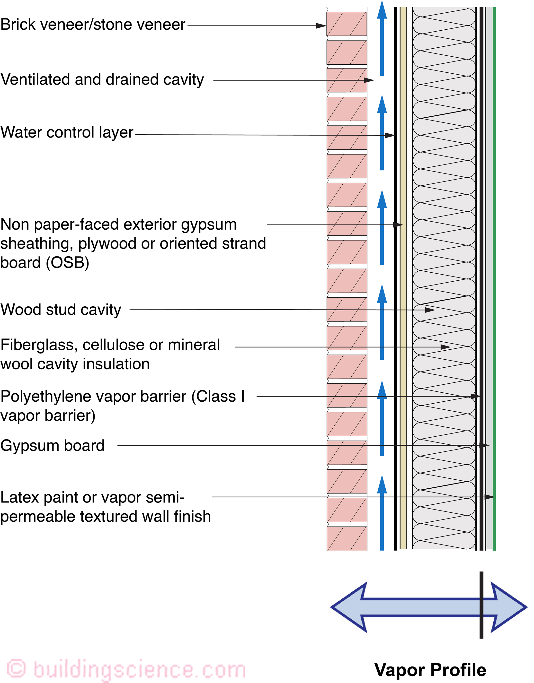
Figure 7: Wood Frame Assembly With Interior Cavity Insulation and Brick or Stone Veneer With an Interior Vapor Control Layer
Applicability
OK: very cold, subarctic and arctic regions.
NO: hot-dry, hot-humid, mixed-dry, mixed-humid, marine, and cold regions
NO: Interior climate class III buildings such as hospitals, museums, and swimming pool enclosures.
Description This wall is a further variation of Figure 5, but now it has a Class I vapor control layer on the interior (a “vapor barrier”) completely eliminating any inward drying. This assembly is considered the “classic” cold climate wall assembly.
Drainage cavity Exterior brick veneer (a “reservoir” cladding) must be uncoupled from the wall assembly with a ventilated and drained cavity. The cavity behind the brick veneer should be at least 1 inch wide and free from mortar droppings. It must also have air inlets (“weep holes”) at its base and air outlets (“weep holes”) at its top in order to provide back ventilation of the brick veneer.
Water control layer Mechanically fastened membrane (building paper or building wrap), vapor-permeable self-adhered membrane, fluid-applied membrane, or integral surface of the sheathing with taped joints.
Air control layer Interior polyethylene, interior gypsum board, exterior gypsum board/structural sheathing, or exterior building wrap (water control layer).
Vapor control layer Class I interior polyethylene on framing.
Thermal control layer Stud bay cavity insulation.
----------------------------------------------------------------------------------------------
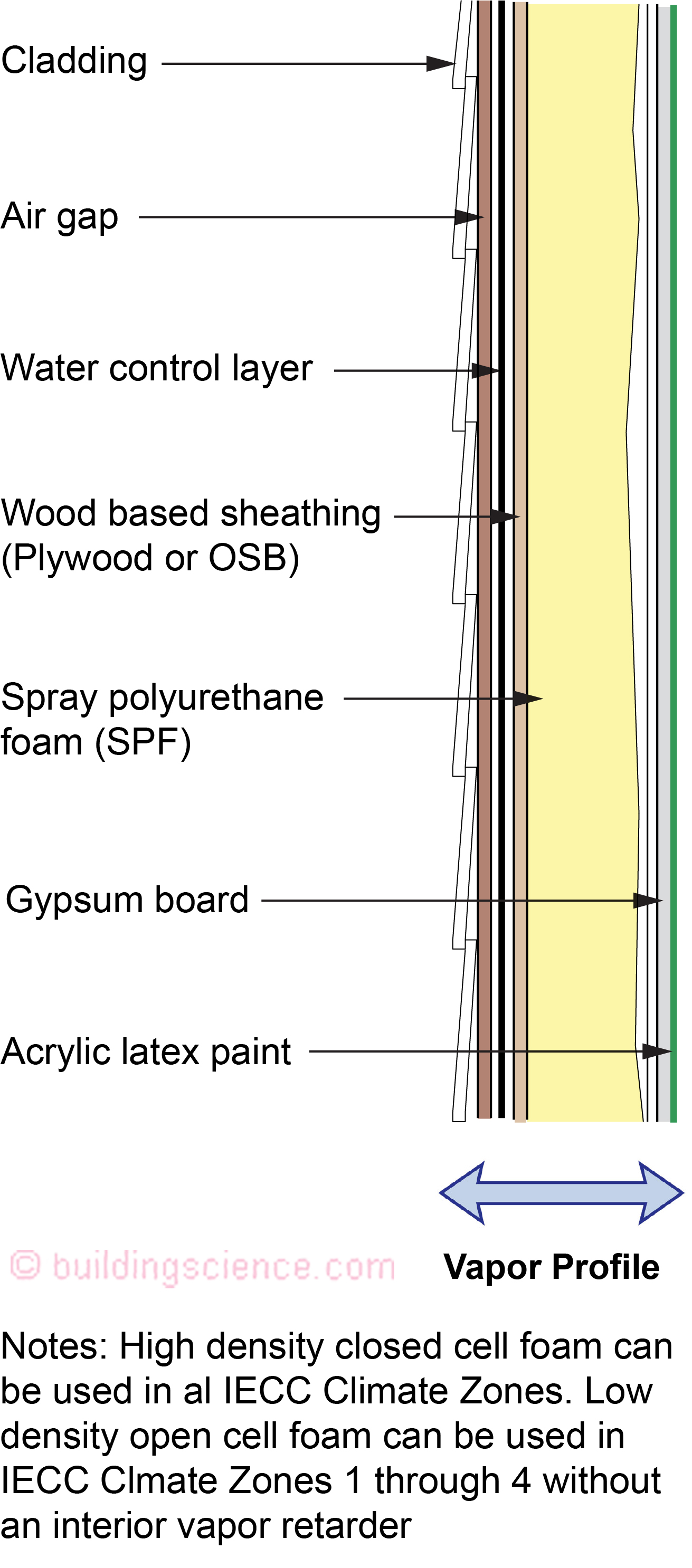
Figure 8: Wood Frame Assembly With Interior Spray Foam Cavity Insulation and Siding
Applicability
OK: hot-dry, hot-humid, mixed-dry, mixed-humid, marine, and cold regions
NO: Very cold and subarctic/arctic regions.
NO: Interior climate class III buildings such as hospitals, museums, and swimming pool enclosures.
Description The spray foam insulation can be low density open cell or high density closed cell spray foam. Both foam types work in most climates.
Drainage cavity The exterior siding should be uncoupled from the wall assembly with a ventilated and drained cavity. The air gap behind the cladding can be provided by using a textured housewrap, a drainage mat, or furring strips at least 3/16 inch thick.
Water control layer Mechanically fastened membrane (building paper or building wrap), vapor-permeable self-adhered membrane, fluid-applied membrane, or integral surface of the sheathing with taped joints. The water control layer in this type of wall should not be a vapor barrier – it should be semi vapor permeable.
Air control layer Stud bay cavity polyurethane spray foam insulation.
Vapor control layer If high density closed cell spray foam, vapor control layer is spray polyurethane foam. If low density open cell spray foam, flow through assembly (controls vapor flow by allowing vapor transfer in both directions).
Interior vapor control Class III latex paint on interior gypsum board. Interior vapor barrier coatings on the gypsum board such as vinyl wallcoverings, oil or alkyd paints should be avoided.
Thermal control layer Stud bay cavity polyurethane spray foam insulation.
----------------------------------------------------------------------------------------------
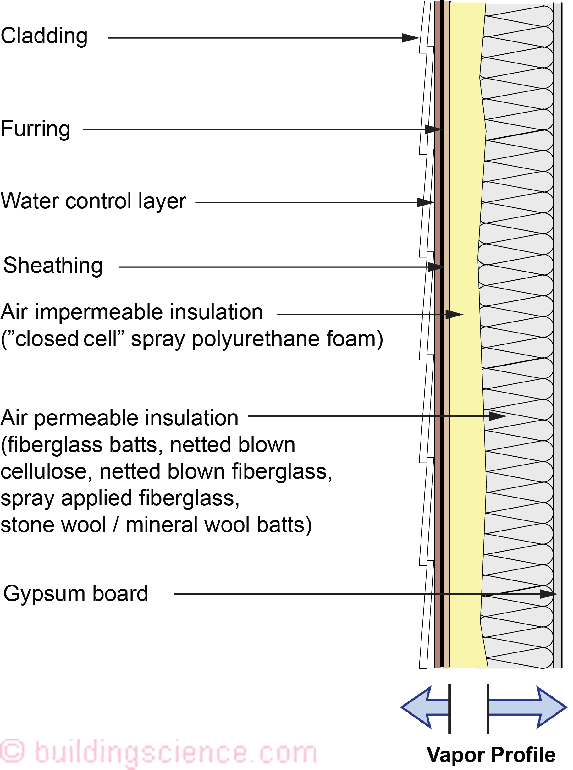
Figure 9: Wood Frame Assembly With Interior Cavity Insulation and Siding
Applicability
OK: hot-dry, hot-humid, mixed-dry, mixed-humid, marine, and cold regions
NO: Very cold and subarctic/arctic regions.
NO: Interior climate class III buildings such as hospitals, museums, and swimming pool enclosures.
Description Figure 9 is a variation of Figure 8, where high density closed cell spray polyurethane foam (air-impermeable insulation) is installed on the interior surface of the exterior sheathing. Then, the remainder of the cavity is filled with fiberglass/cellulose/mineral fiber insulation (air-permeable insulation). The thickness or thermal resistance of the spray foam is based on climate zone and thickness of the wall framing (Table 3).
Drainage cavity The exterior siding should be uncoupled from the wall assembly with a ventilated and drained cavity. The air gap behind the cladding can be provided by using a textured housewrap, a drainage mat, or furring strips at least 3/16 inch thick.
Water control layer Mechanically fastened membrane (building paper or building wrap), vapor-permeable self-adhered membrane, fluid-applied membrane, or integral surface of the sheathing with taped joints. The water control layer in this type of wall should not be a vapor barrier – it should be semi vapor permeable.
Air control layer Stud bay cavity polyurethane spray foam insulation.
Vapor control layer Spray polyurethane foam in stud bay cavities.
Thermal control layer Stud bay cavity polyurethane spray foam insulation and fiberglass/cellulose/mineral fiber.
----------------------------------------------------------------------------------------------
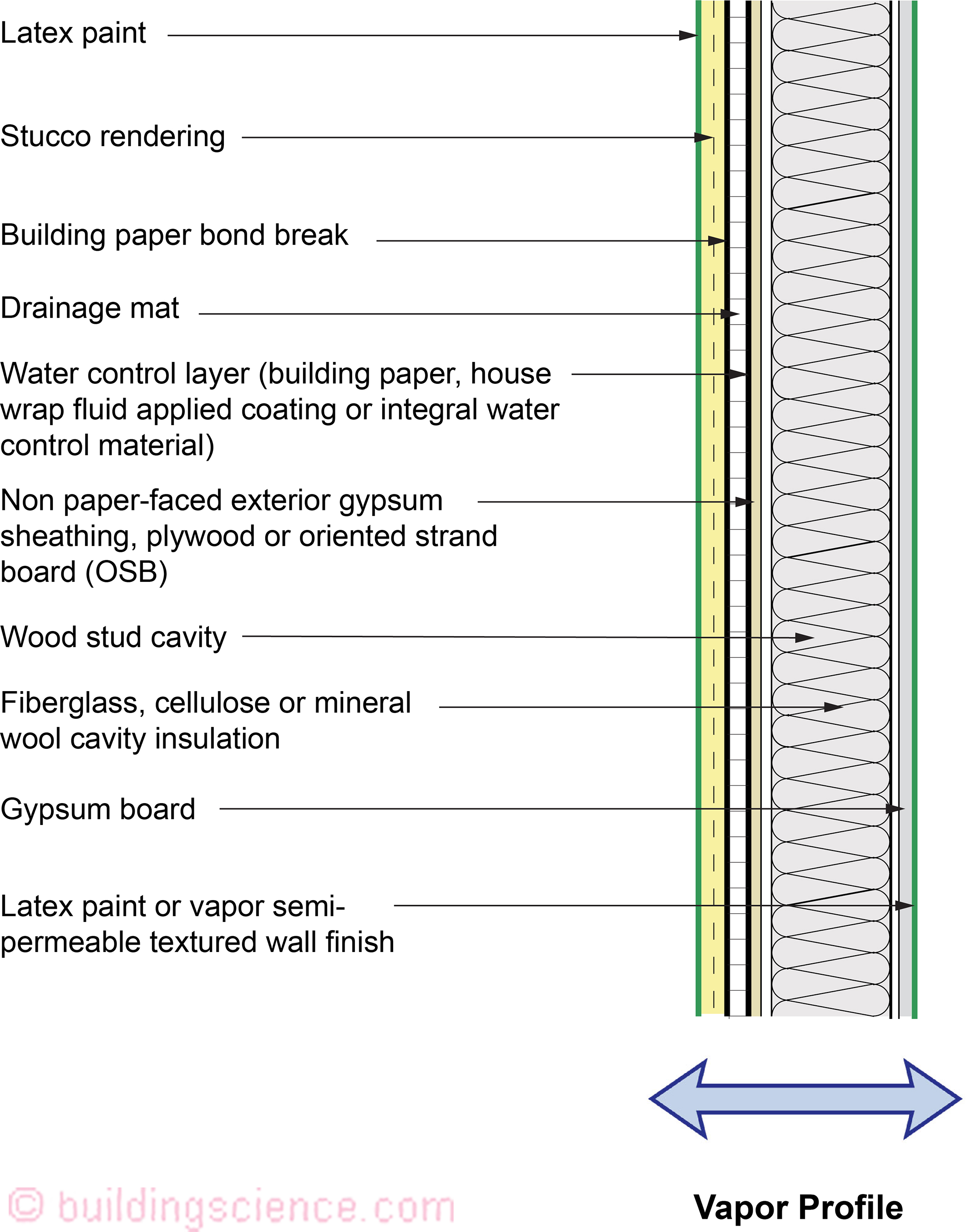
Figure 10: Wood Frame Assembly With Interior Cavity Insulation and Stucco
Applicability
OK: hot-dry, hot-humid, mixed-dry, mixed-humid, marine, and cold regions
NO: Very cold and subarctic/arctic regions.
NO: Interior climate class III buildings such as hospitals, museums, and swimming pool enclosures.
Description This wall is also a flow through assembly similar to Figure 5, but without the brick veneer – it has a stucco cladding. It can dry to both the exterior and the interior.
Drainage cavity This wall assembly must have a drainage space between the stucco rendering and the water control layer. This can be accomplished by installing a drainage mat. Alternately, a textured or profiled water control layer (building wrap) can be used.
Water control layer Mechanically fastened membrane (building paper or building wrap), vapor-permeable self-adhered membrane, fluid-applied membrane, or integral surface of the sheathing with taped joints.
Air control layer Interior gypsum board, exterior stucco rendering, exterior gypsum board/structural sheathing, or exterior building wrap (water control layer).
Vapor control layer No specific vapor control layer. Controls vapor flow by allowing vapor transfer in both directions. Interior vapor control Class III latex paint on interior gypsum board.
Thermal control layer Stud bay cavity insulation.
----------------------------------------------------------------------------------------------

Figure 11: Wood Frame Assembly With Interior Cavity Insulation and Stucco With an Interior Vapor Control Layer
Applicability
OK: cold and very cold regions
NO: hot-dry, hot-humid, mixed-dry, mixed-humid, marine, and subarctic/arctic regions
NO: Interior climate class III buildings such as hospitals, museums, and swimming pool enclosures.
Description This wall is a variation of Figure 10 except it has an interior vapor control layer – a Class II vapor control layer limiting inward drying – but not eliminating it. It still considered a flow through assembly – it can dry to both the exterior and the interior.
Drainage cavity This wall assembly must have a drainage space between the stucco rendering and the water control layer. This can be accomplished by installing a drainage mat. Alternatively, a textured or profiled water control layer (building wrap) can be used.
Water control layer Mechanically fastened membrane (building paper or building wrap), vapor-permeable self-adhered membrane, fluid-applied membrane, or integral surface of the sheathing with taped joints.
Air control layer Interior gypsum board, exterior gypsum board/structural sheathing, or exterior building wrap (water control layer).
Vapor control layer Class II vapor control layer (not Class I/polyethylene or foil). Examples include Kraft facer on the cavity batt insulation or a Class II membrane on the interior side of the framing.
Thermal control layer Stud bay cavity insulation.
----------------------------------------------------------------------------------------------
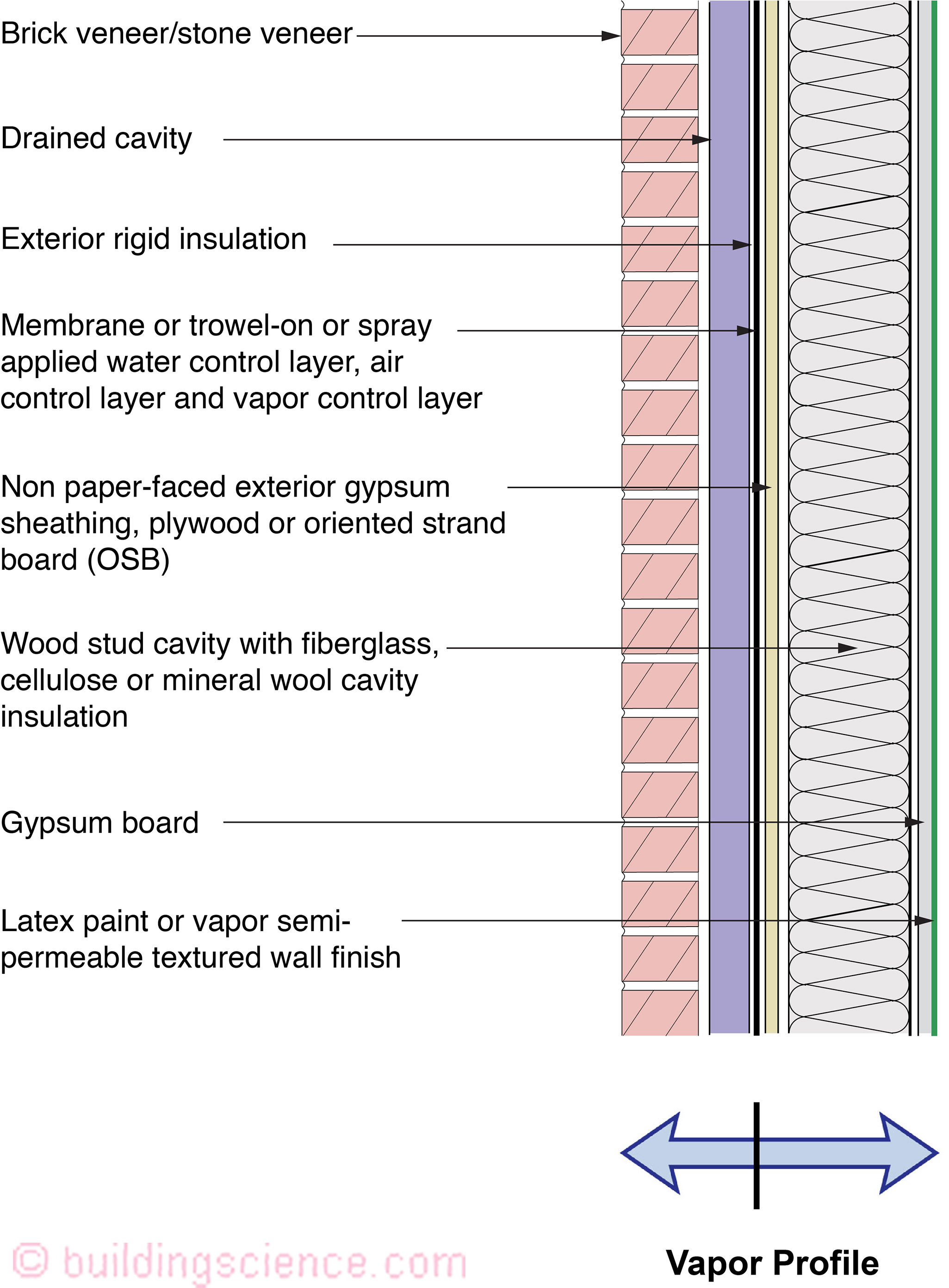
Figure 12: Wood Frame Assembly With Exterior Insulation and Interior Cavity Insulation With Brick or Stone Veneer and No Interior Vapor Control Layer
Applicability
OK: All hygro-thermal regions, all rain exposure zones and interior climate classes I and II.
NO: Interior climate class III buildings such as hospitals, museums, and swimming pool enclosures.
Description This wall has a combined air/vapor/water control layer at the exterior sheathing, inboard of continuous exterior insulation. The sheathing can be non-paper-faced exterior gypsum, plywood, fiberboard, or oriented strand board. This wall assembly will dry from the vapor control layer inwards and will dry from the vapor control layer outwards.
Drainage cavity Hydrostatic pressure is controlled by providing a drainage space behind the cladding. The ideal solution is to decouple the exterior brick veneer (a “reservoir” cladding) from the wall assembly with a ventilated and drained cavity. The cavity behind the brick veneer should be at least 1 inch wide and free from mortar droppings. It must also have air inlets (“weep holes”) at its base and air outlets (“weep holes”) at its top in order to provide back ventilation of the brick veneer. Alternately, in milder or lower-rainfall climates, a ¼ inch drainage mat or drainable insulation can be substituted for the 1 inch air cavity. This option should not be used in IECC Climate Zone 5 and higher, with rainfall over 20 inches per year (due to freeze-thaw risks).
Exterior Insulation Vapor impermeable (foil faced polyisocyanurate) or vapor semi-impermeable (extruded polystyrene) acceptable.
Water control layer Combined air/vapor/water control layer at the exterior sheathing. Can be fully adhered sheet membrane, trowel-on or spray applied coating, mechanically attached sheet, or integral water control layer within the sheathing.
Air control layer Combined air/vapor/water control layer at the exterior sheathing (see above).
Vapor control layer (Exterior) Combined air/vapor/water control layer at the exterior sheathing (see above); vapor impermeable layer at exterior of wall.
Vapor Control Layer (Interior) and Condensation Control In cold climates, condensation is limited on the interior side of the water/air control layer and vapor control layer by installing sufficient exterior thermal insulation on the exterior side of these control layers, and limiting the interior climate class to I and II. In hot-humid climates any moisture that condenses on the exterior side of the water control layer will be drained to the exterior.
This assembly must allow inward drying; therefore, vapor impermeable and vapor semi impermeable interior finishes such as vinyl wall coverings, epoxy paints, and alkyd paints should be avoided. Interior finish is Class III latex paint on interior gypsum board. The thermal resistance of the exterior insulation to avoid condensation is specified in Table 3. This wall assembly is also limited to interior climate class I and II buildings.
Thermal control layer Stud bay cavity insulation and exterior rigid insulation.
----------------------------------------------------------------------------------------------
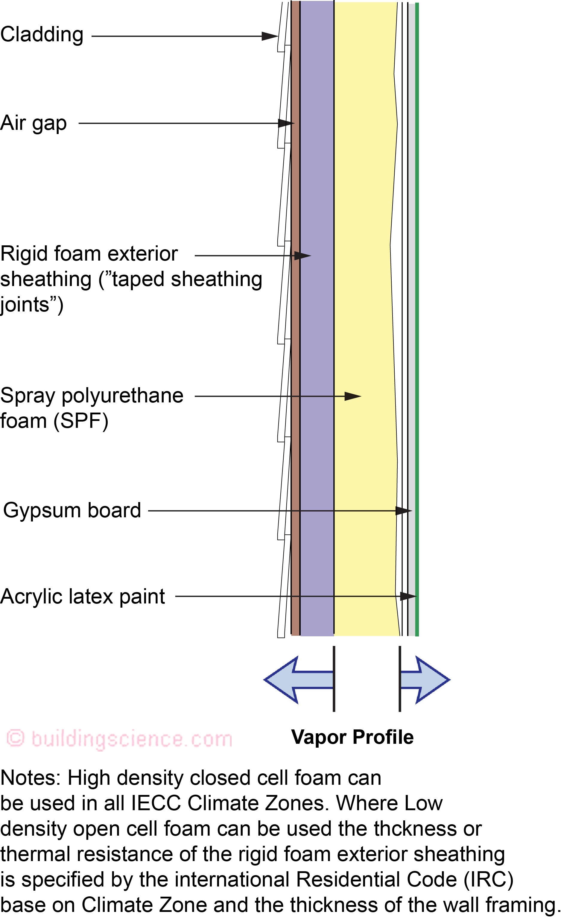
Figure 13: Wood Frame Assembly With Exterior Insulation and Interior Cavity Insulation and Siding
Applicability
OK: hot-dry, hot-humid, mixed-dry, mixed-humid, marine, and cold regions
NO: Very cold and subarctic/arctic regions.
NO: Interior climate class III buildings such as hospitals, museums, and swimming pool enclosures.
Description The cavity insulation in this wall assembly is spray polyurethane foam and is a variation of Figure 8. The spray foam insulation can be low density open cell or high density closed cell spray foam. Both foam types work in most climates.
Drainage cavity The exterior siding should be uncoupled from the wall assembly with a ventilated and drained cavity. The air gap behind the cladding can be provided by using a textured housewrap, a drainage mat, or furring strips at least 3/16 inch thick. If a housewrap is used to create this air gap, it should be semi vapor permeable (i.e., not be a vapor barrier).
Exterior Insulation Vapor impermeable (foil faced polyisocyanurate) or vapor semi-impermeable (extruded polystyrene) acceptable.
Water control layer Taped joints of the exterior rigid insulation (typical).
Air control layer Spray polyurethane foam in stud bay cavities.
Vapor control layer If high density closed cell spray foam, vapor control layer is spray polyurethane foam. If low density open cell spray foam, vapor control is provided by controlling the temperature of the condensing surface, as a result of installing exterior thermal insulation of sufficient thermal resistance as well as by limiting the interior climate class to I and II. With low density open cell spray foam, the thickness (thermal resistance) of the rigid foam exterior sheathing is based on climate zone and thickness of the wall framing (Table 3). Interior vapor barrier coatings on the gypsum board such as vinyl wallcoverings, oil or alkyd paints should be avoided.
Thermal control layer Stud bay cavity insulation and exterior rigid insulation.
----------------------------------------------------------------------------------------------
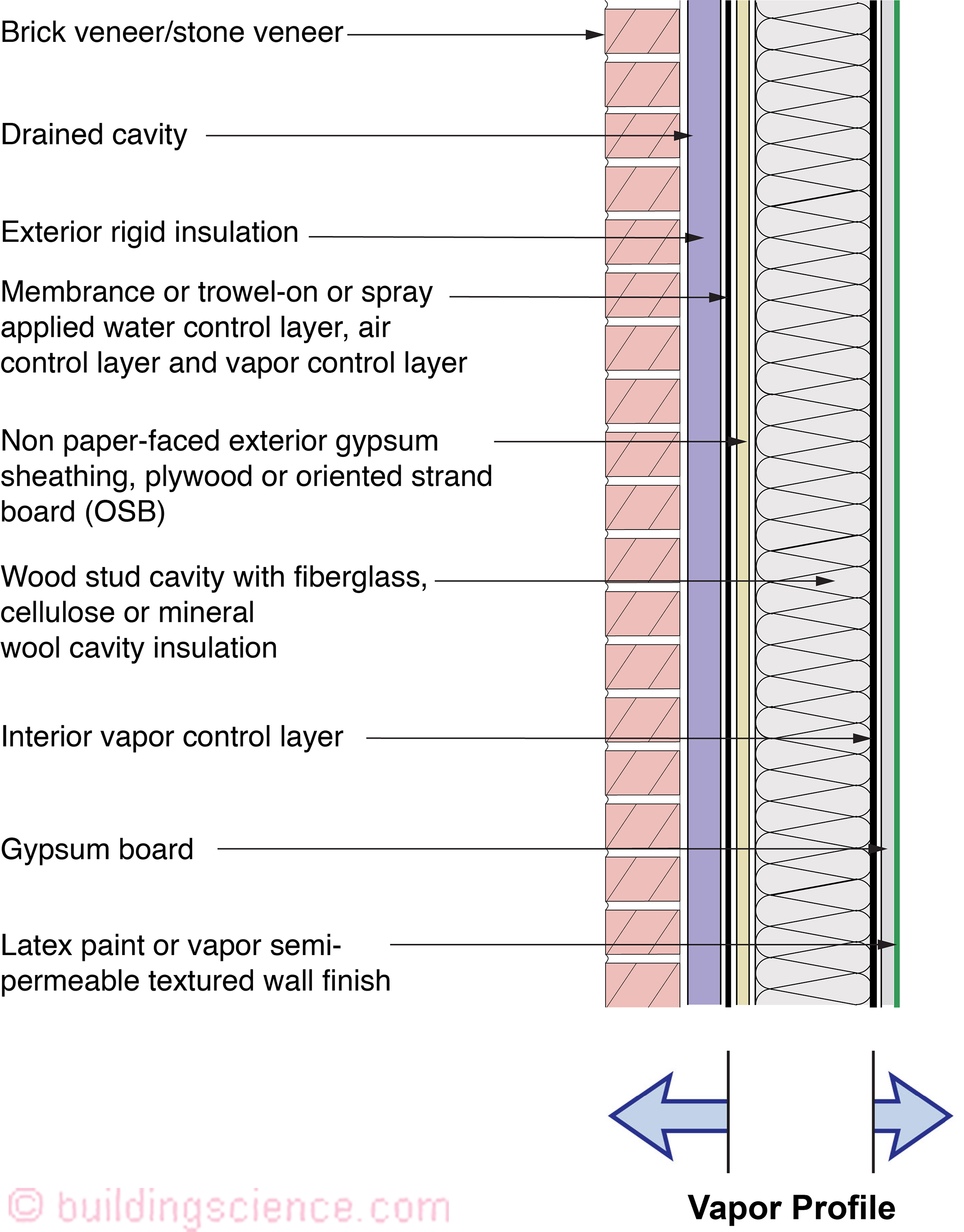
Figure 14: Wood Frame Assembly With Exterior Insulation and Interior Cavity Insulation With Brick or Stone Veneer and an Interior Vapor Control Layer
Applicability
OK: cold and very cold regions
NO: hot-dry, hot-humid, mixed-dry, mixed-humid, marine, and subarctic/arctic regions
NO: Interior climate class III buildings such as hospitals, museums, and swimming pool enclosures.
Description This wall is a variation of Figure 12, but with an interior vapor control layer. This wall has a combined air/vapor/water control layer at the exterior sheathing, inboard of continuous exterior insulation. The sheathing can be non-paper-faced exterior gypsum, plywood, fiberboard, or oriented strand board. This wall assembly will dry from the vapor control layer inwards and will dry from the vapor control layer outwards.
Drainage cavity Hydrostatic pressure is controlled by providing a drainage space behind the cladding. The ideal solution is to decouple the exterior brick veneer (a “reservoir” cladding) from the wall assembly with a ventilated and drained cavity. The cavity behind the brick veneer should be at least 1 inch wide and free from mortar droppings. It must also have air inlets (“weep holes”) at its base and air outlets (“weep holes”) at its top in order to provide back ventilation of the brick veneer.
Exterior Insulation Vapor impermeable (foil faced polyisocyanurate) or vapor semi-impermeable (extruded polystyrene) acceptable.
Water control layer Combined air/vapor/water control layer at the exterior sheathing. Can be fully adhered sheet membrane, trowel-on or spray applied coating, mechanically attached sheet, or integral water control layer within the sheathing.
Air control layer Combined air/vapor/water control layer at the exterior sheathing (see above).
Vapor control layer (Exterior) Combined air/vapor/water control layer at the exterior sheathing (see above); vapor impermeable layer at exterior of wall.
Vapor Control Layer (Interior) and Condensation Control This wall assembly has an interior vapor control layer; therefore, the wall assembly cannot dry to the interior. Nor can this wall assembly dry to the exterior. Therefore, this wall assembly is limited to interior climate class I and II buildings, and is limited to cold, very cold and colder hygro-thermal regions.
Thermal control layer Stud bay cavity insulation and exterior rigid insulation.
---------------------------------------------------------------------------------------------- 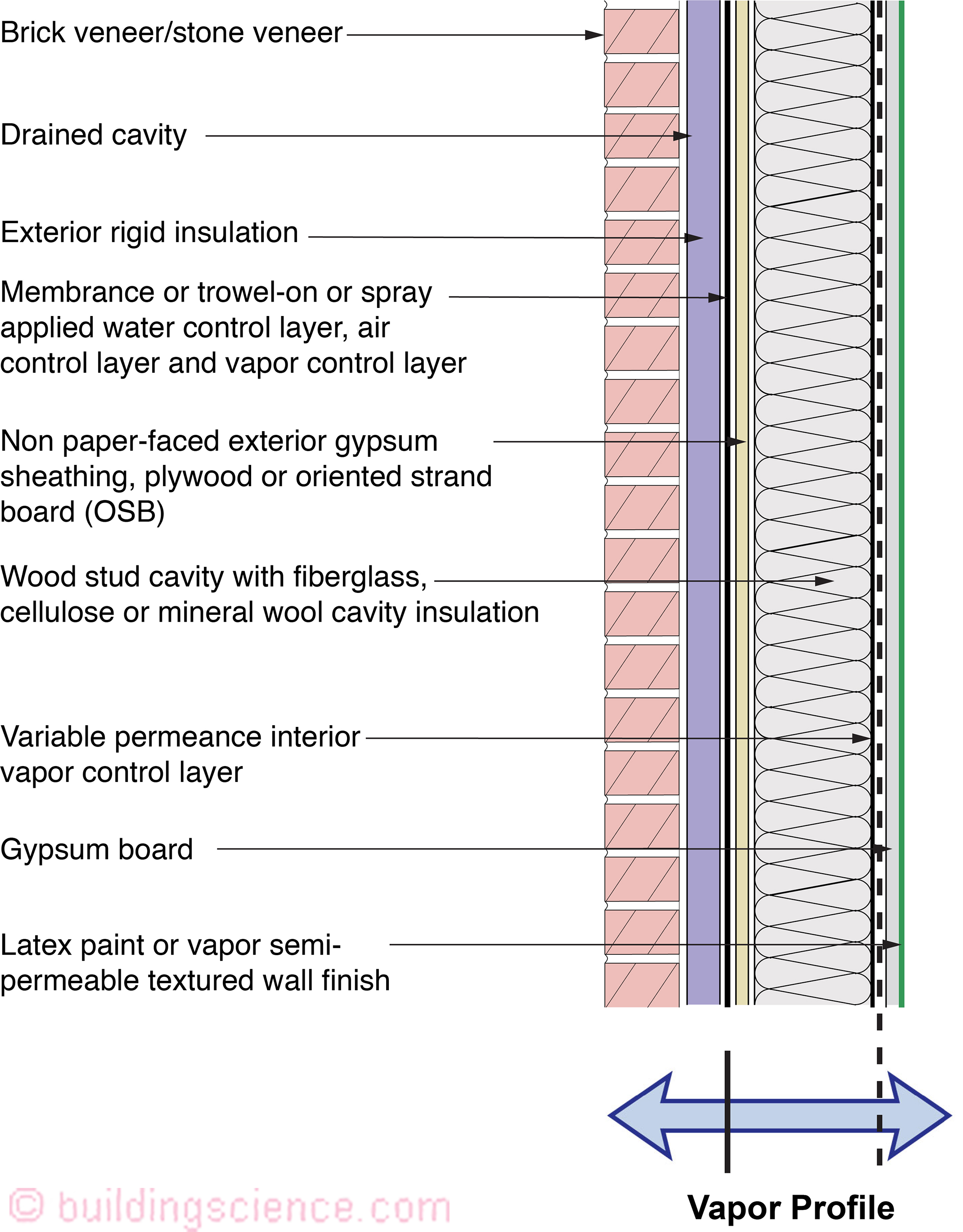
Figure 15: Wood Frame Assembly With Exterior Insulation and Interior Cavity Insulation With Brick or Stone Veneer and a Smart Interior Vapor Control Layer or Kraft Faced Cavity Insulation
Applicability
OK: Marine, Cold, Very Cold, and colder hygro-thermal regions
OK: All rain exposure zones and interior climate classes I and II.
NO: Interior climate class III buildings such as hospitals, museums, and swimming pool enclosures.
Description This wall is a variation of Figure 14, but with a variable permeance (“smart”) vapor control layer or kraft faced batt insulation (also a “smart” vapor control layer). This wall is designed to dry to the interior. The sheathing can be non-paper-faced exterior gypsum, plywood, fiberboard, or oriented strand board.
Drainage cavity Hydrostatic pressure is controlled by providing a drainage space behind the cladding. The ideal solution is to decouple the exterior brick veneer (a “reservoir” cladding) from the wall assembly with a ventilated and drained cavity. The cavity behind the brick veneer should be at least 1 inch wide and free from mortar droppings. It must also have air inlets (“weep holes”) at its base and air outlets (“weep holes”) at its top in order to provide back ventilation of the brick veneer.
Exterior Insulation Vapor impermeable (foil faced polyisocyanurate) or vapor semi-impermeable (extruded polystyrene) acceptable.
Water control layer Combined air/vapor/water control layer at the exterior sheathing. Can be fully adhered sheet membrane, trowel-on or spray applied coating, mechanically attached sheet, or integral water control layer within the sheathing.
Air control layer Combined air/vapor/water control layer at the exterior sheathing (see above).
Vapor control layer (Exterior) Combined air/vapor/water control layer at the exterior sheathing (see above); vapor impermeable layer at exterior of wall.
Vapor Control Layer (Interior) and Condensation Control This wall assembly has a variable permeance (“smart”) vapor control layer or kraft-faced batt insulation (also a “smart” vapor control layer). This layer changes its vapor transmission based on interior relative humidity. It therefore allows inward drying during the summer months, or if the wall cavity becomes wet from exterior sources. Even with inward drying, this wall assembly should be limited to interior climate class I and II buildings. Despite the effectiveness of the variable permeance interior vapor control layer, this wall assembly should still be limited to marine, cold, very cold, and colder hygro-thermal regions.
Thermal control layer Stud bay cavity insulation and exterior rigid insulation.
----------------------------------------------------------------------------------------------
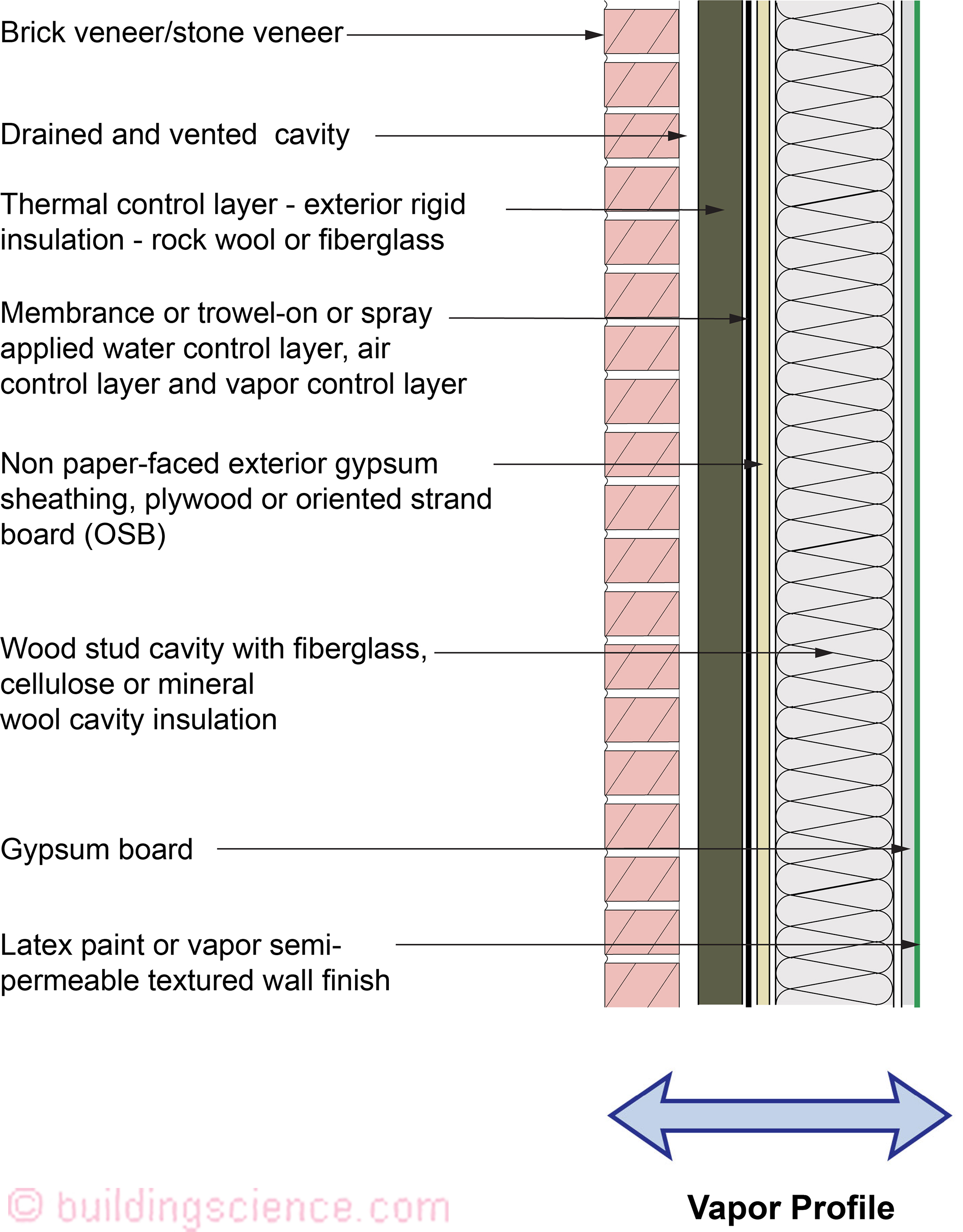
Figure 16: Wood Frame Assembly With Exterior Insulation and Interior Cavity Insulation With Brick or Stone Veneer and No Interior Vapor Control Layer
Applicability
OK: All hygro-thermal regions
OK: All rain exposure zones and interior climate classes I and II.
NO: Interior climate class III buildings such as hospitals, museums, and swimming pool enclosures.
Description This wall assembly is a flow through assembly that can dry in both directions. The sheathing can be non-paper-faced exterior gypsum, plywood, fiberboard, or oriented strand board.
Drainage cavity Hydrostatic pressure is controlled by providing a drainage space behind the cladding. The ideal solution is to decouple the exterior brick veneer (a “reservoir” cladding) from the wall assembly with a ventilated and drained cavity. The cavity behind the brick veneer should be at least 1 inch wide and free from mortar droppings. It must also have air inlets (“weep holes”) at its base and air outlets (“weep holes”) at its top in order to provide back ventilation of the brick veneer. Alternately, in milder or lower-rainfall climates, a ¼ inch drainage mat or drainable insulation can be substituted for the 1 inch air cavity. This option should not be used in IECC Climate Zone 5 and higher, with rainfall over 20 inches per year (due to freeze-thaw risks).
Exterior Insulation Vapor permeable (mineral wool or rigid fiberglass insulation) required.
Water control layer Combined air/vapor/water control layer at the exterior sheathing. Can be fully adhered sheet membrane, trowel-on or spray applied coating, mechanically attached sheet, or integral water control layer within the sheathing.
Air control layer Combined air/vapor/water control layer at the exterior sheathing (see above).
Vapor control layer (Exterior) Combined air/vapor/water control layer at the exterior sheathing (see above). The vapor control layer is vapor permeable. Where the annual average rainfall exceeds 20 inches and a reservoir cladding such as brick or stone veneer is used, the vapor control layer should be vapor semi permeable (or less in permeance) to control inward vapor drive.
Vapor Control Layer (Interior) and Condensation Control This wall assembly does not have an interior vapor control layer (Class III latex paint only); therefore, the thermal resistance of the exterior insulation to avoid condensation is specified in Table 3. This wall assembly is also limited to interior climate class I and II buildings. This assembly can dry inwards – therefore vapor impermeable and vapor semi impermeable interior finishes such as vinyl wall coverings, epoxy paints, and alkyd paints should be avoided.
Thermal control layer Stud bay cavity insulation and exterior rigid insulation.
----------------------------------------------------------------------------------------------
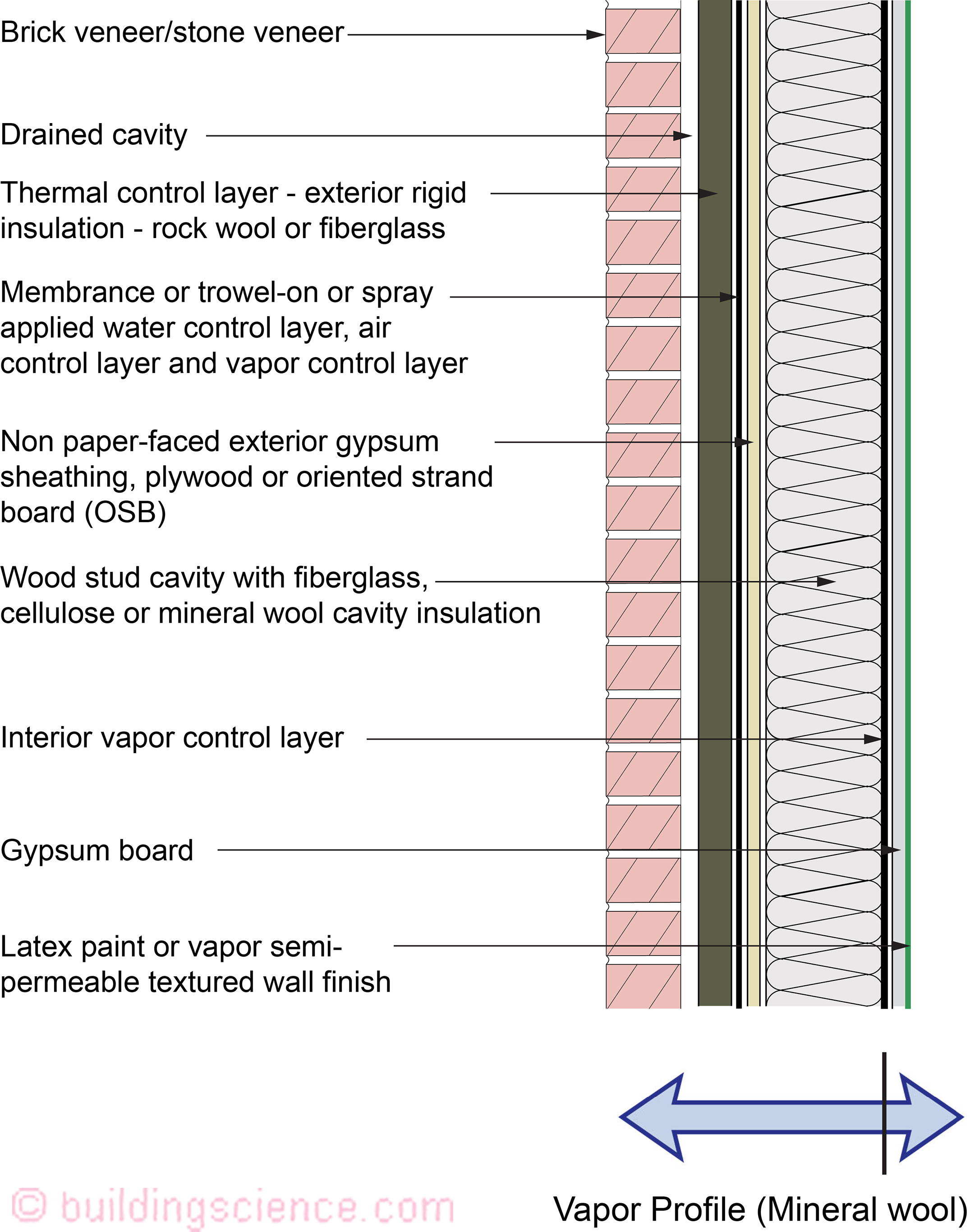
Figure 17: Wood Frame Assembly With Exterior Insulation and Interior Cavity Insulation With Brick or Stone Veneer and an Interior Vapor Control Layer
Applicability
OK: Marine, Cold, Very Cold, and colder hygro-thermal regions
OK: All rain exposure zones and interior climate classes I and II.
NO: Interior climate class III buildings such as hospitals, museums, and swimming pool enclosures.
Description This wall is a variation of Figure 16, but with an interior vapor control layer. The sheathing can be non-paper-faced exterior gypsum, plywood, fiberboard, or oriented strand board.
Drainage cavity Hydrostatic pressure is controlled by providing a drainage space behind the cladding. The ideal solution is to decouple the exterior brick veneer (a “reservoir” cladding) from the wall assembly with a ventilated and drained cavity. The cavity behind the brick veneer should be at least 1 inch wide and free from mortar droppings. It must also have air inlets (“weep holes”) at its base and air outlets (“weep holes”) at its top in order to provide back ventilation of the brick veneer.
Exterior Insulation Vapor permeable (mineral wool or rigid fiberglass insulation) required.
Water control layer Combined air/vapor/water control layer at the exterior sheathing. Can be fully adhered sheet membrane, trowel-on or spray applied coating, mechanically attached sheet, or integral water control layer within the sheathing.
Air control layer Combined air/vapor/water control layer at the exterior sheathing (see above).
Vapor control layer (Exterior) Combined air/vapor/water control layer at the exterior sheathing (see above). The vapor control layer is vapor permeable. Where the annual average rainfall exceeds 20 inches and a reservoir cladding such as brick or stone veneer is used, the vapor control layer should be vapor semi permeable (or less in permeance) to control inward vapor drive.
Vapor Control Layer (Interior) and Condensation Control Although this wall assembly includes an interior vapor control layer, the recommended construction uses thermal resistance of exterior insulation to control condensation, as specified in Table 3. This wall assembly is also limited to interior climate class I and II buildings. This wall assembly has an interior vapor control layer; therefore, the wall assembly cannot dry to the interior. However, this wall assembly can dry to the exterior. Because of the interior vapor control layer, this wall assembly should be limited to cold, very cold, and colder hygro-thermal regions.
Thermal control layer Stud bay cavity insulation and exterior rigid insulation.
----------------------------------------------------------------------------------------------
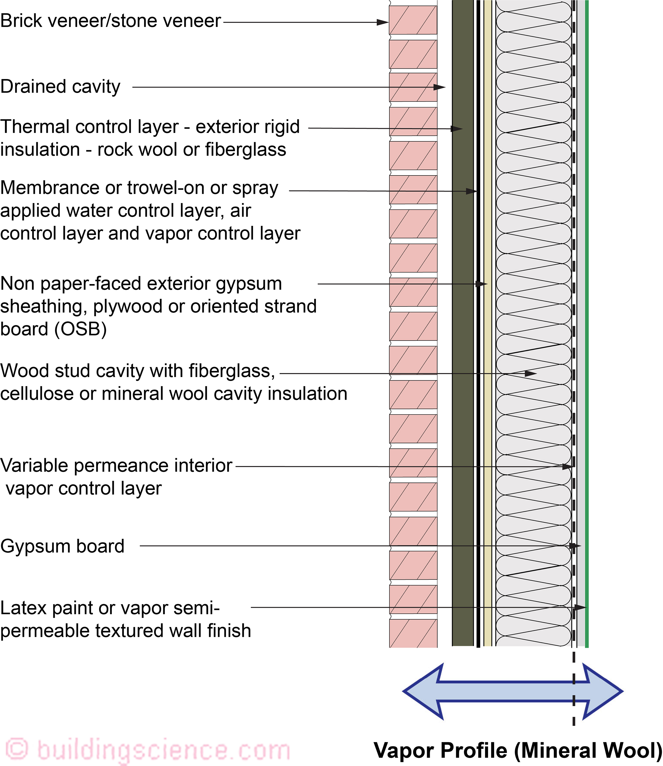
Figure 18: Wood Frame Assembly With Exterior Insulation and Interior Cavity Insulation With Brick or Stone Veneer and a Smart Interior Vapor Control Layer or Kraft Faced Cavity Insulation
Applicability
OK: Marine, Cold, Very Cold, and colder hygro-thermal regions
OK: All rain exposure zones and interior climate classes I and II.
NO: Interior climate class III buildings such as hospitals, museums, and swimming pool enclosures.
Description This wall is a variation of Figure 17, but with a variable permeance (“smart”) vapor control layer or kraft faced batt insulation (also a “smart” vapor control layer). This wall is designed to dry to the interior. The sheathing can be non-paper-faced exterior gypsum, plywood, fiberboard, or oriented strand board.
Drainage cavity Hydrostatic pressure is controlled by providing a drainage space behind the cladding. The ideal solution is to decouple the exterior brick veneer (a “reservoir” cladding) from the wall assembly with a ventilated and drained cavity. The cavity behind the brick veneer should be at least 1 inch wide and free from mortar droppings. It must also have air inlets (“weep holes”) at its base and air outlets (“weep holes”) at its top in order to provide back ventilation of the brick veneer.
Exterior Insulation Vapor permeable (mineral wool or rigid fiberglass insulation) required.
Water control layer Combined air/vapor/water control layer at the exterior sheathing. Can be fully adhered sheet membrane, trowel-on or spray applied coating, mechanically attached sheet, or integral water control layer within the sheathing.
Air control layer Combined air/vapor/water control layer at the exterior sheathing (see above).
Vapor control layer (Exterior) Combined air/vapor/water control layer at the exterior sheathing (see above). The vapor control layer is vapor permeable. Where the annual average rainfall exceeds 20 inches and a reservoir cladding such as brick or stone veneer is used, the vapor control layer should be vapor semi permeable (or less in permeance) to control inward vapor drive.
Vapor Control Layer (Interior) and Condensation Control This wall assembly has a variable permeance (“smart”) vapor control layer or kraft-faced batt insulation (also a “smart” vapor control layer). This layer changes its vapor transmission based on interior relative humidity. It therefore allows inward drying during the summer months, or if the wall cavity becomes wet from exterior sources. Even with inward drying, this wall assembly should be limited to interior climate class I and II buildings. Despite the effectiveness of the variable permeance interior vapor control layer, this wall assembly should still be limited to marine, cold, very cold, and colder hygro-thermal regions.
Thermal control layer Stud bay cavity insulation and exterior rigid insulation.
----------------------------------------------------------------------------------------------
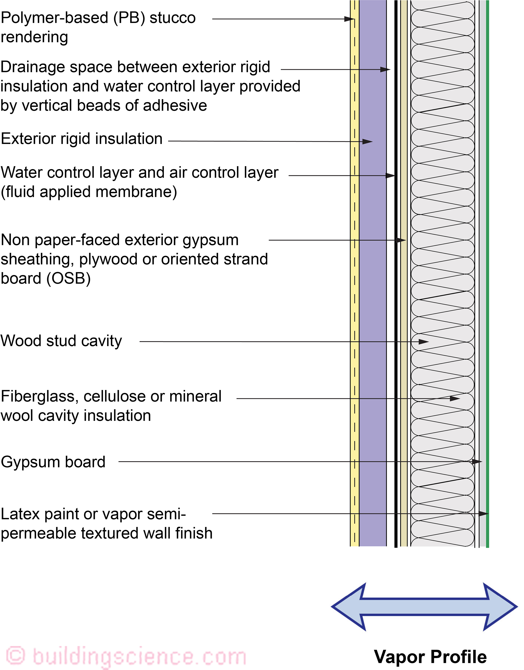
Figure 19: Wood Frame Assembly With Exterior Insulation and Interior Cavity Insulation With Synthetic Stucco (EIFS)
Applicability
OK: All hygro-thermal regions except subarctic/arctic
OK: All rain exposure zones and interior climate classes I and II.
NO: Interior climate class III buildings such as hospitals, museums, and swimming pool enclosures.
Description This is a water managed exterior insulation finish system (EIFS) wall. Unlike “face-sealed” EIFS, this wall has a water control layer inboard of the exterior stucco skin that is drained to the exterior. It is also a flow through assembly that can dry to both the exterior and the interior.
Drainage cavity This wall assembly requires a drainage space between the exterior rigid insulation and the water control layer. This can be accomplished by installing vertical beads of adhesive to adhere the exterior rigid insulation to the sheathing.
Exterior Insulation Vapor semi-permeable (expanded polystyrene/EPS) required.
Water control layer Combined air/water control layer at the exterior sheathing; fluid applied membrane compatible with EIFS system adhesive.
Air control layer Combined air/water control layer at the exterior sheathing (see above).
Vapor Control Layer (Interior) and Condensation Control This wall assembly does not have an interior vapor control layer (Class III latex paint only); therefore, the thermal resistance of the exterior insulation to avoid condensation is specified in Table 3. This wall assembly is also limited to interior climate class I and II buildings. In hot-humid climates, any moisture that condenses on the exterior side of the water control layer will be drained to the exterior. This assembly can dry inwards – therefore vapor impermeable and vapor semi impermeable interior finishes such as vinyl wall coverings, epoxy paints, and alkyd paints should be avoided.
Thermal control layer Stud bay cavity insulation and exterior rigid insulation.
----------------------------------------------------------------------------------------------
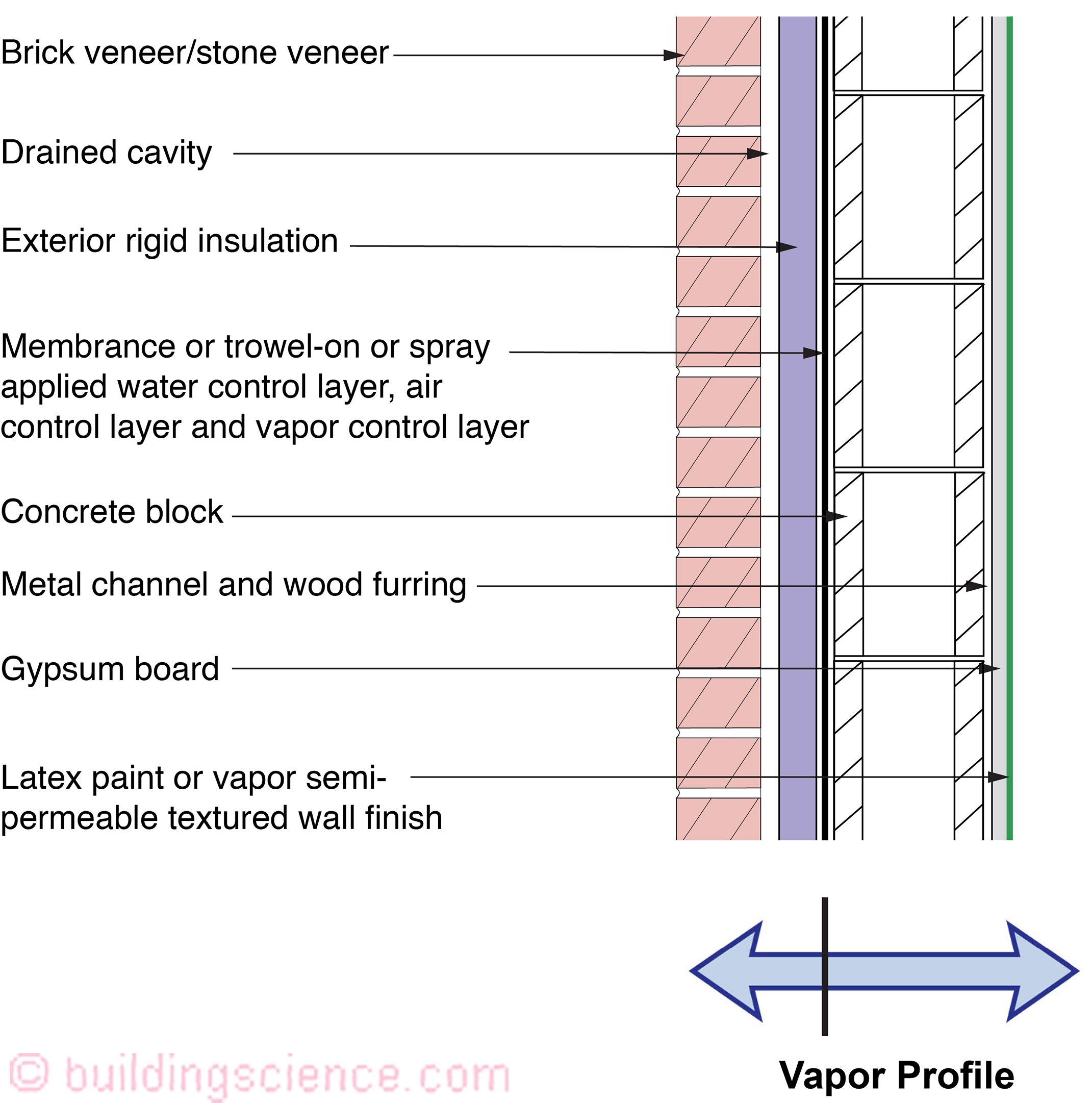
Figure 20: Concrete Masonry Unit (CMU) With Exterior Insulation and Brick or Stone Veneer and Vapor Impermeable/Semi-Permeable Insulation
Applicability
OK: All hygro-thermal regions
OK: All rain exposure zones
OK: All interior climate (classes I, II, and III)
Description This wall is an implementation of the ‘perfect wall,’ with all insulation outboard of the structure, and a combined air/vapor/water control layer at the CMU surface, inboard of continuous exterior insulation.
Drainage cavity Hydrostatic pressure is controlled by providing a drainage space behind the cladding. The ideal solution is to decouple the exterior brick veneer (a “reservoir” cladding) from the wall assembly with a ventilated and drained cavity. The cavity behind the brick veneer should be at least 1 inch wide and free from mortar droppings. It must also have air inlets (“weep holes”) at its base and air outlets (“weep holes”) at its top in order to provide back ventilation of the brick veneer.
Exterior Insulation Vapor impermeable (foil faced polyisocyanurate) or vapor semi-impermeable (extruded polystyrene) acceptable.
Water control layer Combined air/vapor/water control layer at the exterior of CMU. Can be fully adhered sheet membrane or trowel-on or spray applied coating.
Air control layer Combined air/vapor/water control layer at the exterior of CMU (see above).
Vapor control layer (Exterior) Combined air/vapor/water control layer at the exterior of CMU (see above); vapor impermeable.
Vapor Control Layer (Interior) and Condensation Control Interior latex paint (Class III) on interior finishes. In cold climates, condensation is limited on the interior side of the air/water/vapor control layer by installing all of the thermal insulation on the exterior side of these control layers. In hot-humid climates, any moisture that condenses on the exterior side of the air/water control layer will be drained to the exterior. This wall assembly will dry from the vapor control layer inwards and will dry from the vapor control layer outwards.
Thermal control layer Continuous exterior rigid insulation.
----------------------------------------------------------------------------------------------
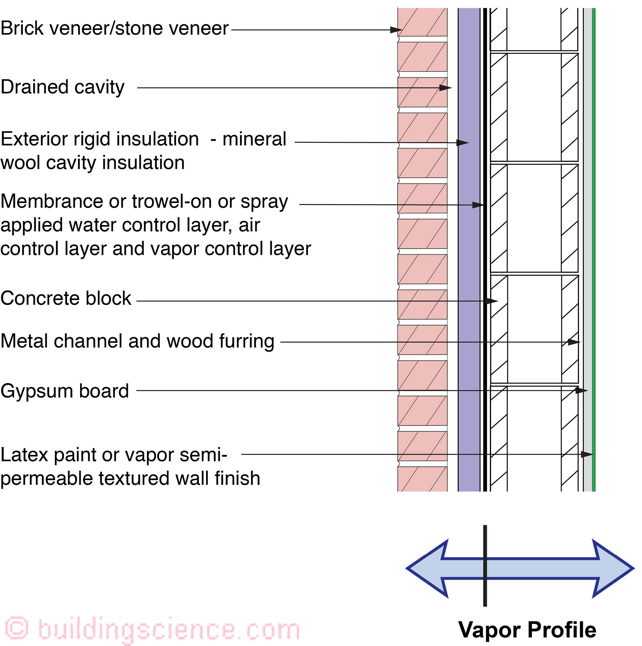
Figure 21: Concrete Masonry Unit (CMU) With Exterior Insulation and Brick or Stone Veneer and Vapor Permeable Insulation
Applicability
OK: All hygro-thermal regions
OK: All rain exposure zones
OK: All interior climate (classes I, II, and III)
Description This wall is an implementation of the ‘perfect wall,’ with all insulation outboard of the structure, and a combined air/vapor/water control layer at the CMU surface, inboard of continuous exterior insulation.
Drainage cavity Hydrostatic pressure is controlled by providing a drainage space behind the cladding. The ideal solution is to decouple the exterior brick veneer (a “reservoir” cladding) from the wall assembly with a ventilated and drained cavity. The cavity behind the brick veneer should be at least 1 inch wide and free from mortar droppings. It must also have air inlets (“weep holes”) at its base and air outlets (“weep holes”) at its top in order to provide back ventilation of the brick veneer.
Exterior Insulation Vapor permeable (mineral wool or rigid fiberglass insulation) required.
Water control layer Combined air/vapor/water control layer at the exterior of CMU. Can be fully adhered sheet membrane or trowel-on or spray applied coating.
Air control layer Combined air/vapor/water control layer at the exterior of CMU (see above).
Vapor control layer (Exterior) Combined air/vapor/water control layer at the exterior of CMU (see above). The vapor control layer can either be vapor impermeable or vapor permeable. Where the annual average rainfall exceeds 20 inches and a reservoir cladding such as brick or stone veneer is used, the vapor control layer should be vapor semi permeable (or less in permeance) to control inward vapor drive.
Vapor Control Layer (Interior) and Condensation Control Interior latex paint (Class III) on interior finishes. In cold climates, condensation is limited on the interior side of the air/water/vapor control layer by installing all of the thermal insulation on the exterior side of these control layers. In hot-humid climates, any moisture that condenses on the exterior side of the air/water control layer will be drained to the exterior. This wall assembly will dry from the vapor control layer inwards and will dry from the vapor control layer outwards. If a vapor permeable vapor control layer is used coupled with mineral wool insulation through wall vapor flow occurs – the wall assembly dries in both directions depending on the moisture gradient.
Thermal control layer Continuous exterior rigid insulation.
----------------------------------------------------------------------------------------------
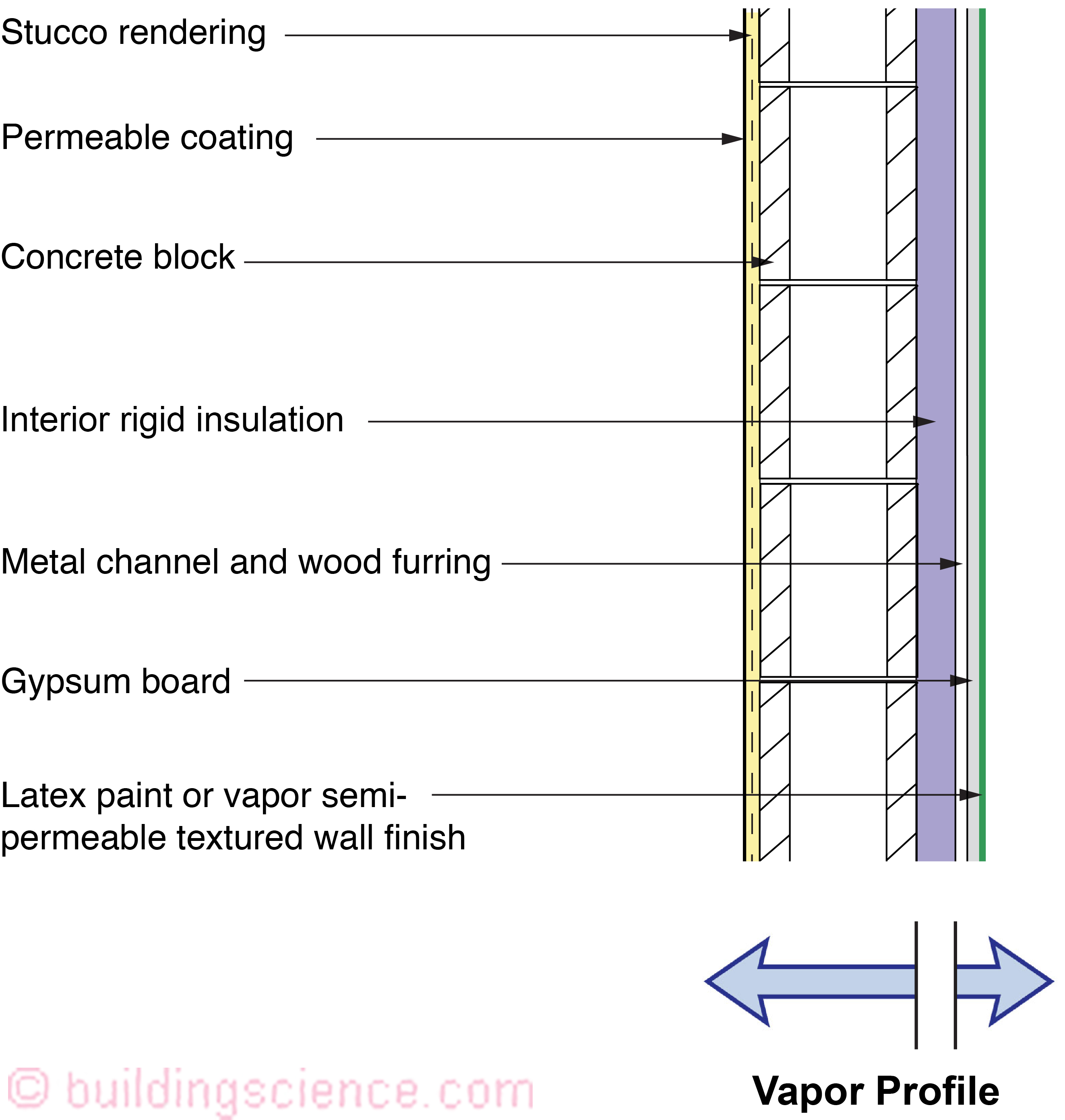
Figure 22: Concrete Masonry Unit (CMU) With Interior Rigid Insulation and Stucco
Applicability
OK: All hygro-thermal regions except subarctic/arctic
OK: All rain exposure zones and interior climate classes I and II
OK: Interior climate class III buildings such as hospitals, museums, and swimming pool enclosures in hot-dry, hot-humid, and mixed-dry hygro-thermal regions
NO: Interior climate class III buildings such as hospitals, museums, and swimming pool enclosures in all other hygro-thermal regions
Description This wall has continuous rigid insulation on the inboard side of the CMU wall. This wall assembly therefore has all of the thermal insulation installed to the interior of the water, air, and vapor control layers. This wall assembly will dry from the vapor control layer inwards and will dry from the vapor control layer outwards.
Drainage cavity n/a
Exterior Insulation n/a
Water control layer Painted stucco rendering on CMU. The CMU wall behaves as a “mass wall,” storing moisture during rain events, then drying during more favorable periods.
Air control layer Painted stucco rendering on CMU.
Vapor Control Layer and Condensation Control Extruded polystyrene insulation (XPS) inboard of CMU wall. The thermal insulation is not air permeable and is vapor semi impermeable. Therefore, it can also be used in marine, cold regions or colder with the limitation of interior climate class I and II buildings.
Thermal control layer Continuous interior rigid insulation; extruded polystyrene insulation (XPS) inboard of CMU wall.
* In August, 2004, the ASHRAE Journal ran a paper I wrote “Understanding Vapor Barriers”. After almost 2 decades I thought I would update it and focus it on rain and air control as well as vapor control – all things that “walls” need to do... hence the revised title “Understanding Walls”…