The control of air flow is important for several reasons: to control moisture damage, reduce energy losses, and to ensure occupant comfort and health. Airflow across the building enclosure is driven by wind pressures, stack effect, and mechanical air handling equipment like fans and furnaces. A continuous, strong, stiff, durable and air impermeable air barrier system is required between the exterior and conditioned space to control airflow driven by these forces.
Introduction
It has long been recognised that the control of air flow is a crucial and intrinsic part of heat and moisture control in modern building enclosures [Wilson 1963, Garden 1965]. That this statement is true for all climates has been a more recently developed awareness [Lstiburek 1994]. A large fraction of a modern, well-insulated building's space conditioning energy load is due to uncontrolled air leakage. Wintertime condensation of water vapor in exfiltrating air (or summertime condensation of infiltrating air) within assemblies is one of the two major sources of moisture in the above-grade enclosure (driving rain being the other). Air flow through the enclosure can also carry, exhaust gases, odours, and sounds through enclosures as well as mold spores and off gassing generated within the enclosure. Uncontrolled air leakage through the enclosure is therefore often a major cause of performance (e.g. comfort, health, energy, durability, etc.) problems.
Water vapor diffusion, while amenable to simple analysis, is often (but definitely not always) an insignificant source of moisture in modern building envelopes. Wintertime exfiltration condensation is, however, acknowledged as a common building performance problem in cold climates. Warm weather infiltration condensation is often a problem in warm and humid climates (e.g. the south-eastern States) and in some cases in cool climates, especially when air conditioning or cooling (e.g. arenas) is used.
Therefore, there are three primary classes of reasons why the control of air flow is important to building performance:
Moisture control – water vapor in the air can be deposited within the envelope by condensation and cause serious health, durability, and performance problems.
Energy savings –air leaking out of a building must be replaced with outdoor air which requires energy to condition it. Approximately 30% to 50% of space conditioning energy consumption in many well-insulated buildings is due to air leakage through the building enclosure. Convective circulation and wind washing both reduce the effectiveness of thermal insulation and thus increase energy transfer across the envelope.
Comfort and health – cold drafts and the excessively dry wintertime air that results from excessive air leakage directly affect human comfort, wind-cooled portions of the interior of the enclosure promote condensation which supports biological growth which in turn affects indoor air quality, airborne sound transmission control requires good airflow control, and odors and gases from outside and adjoining buildings often annoy or cause health problems.
There are other circumstances that require the control of air flow; for example, to control smoke and fire spread through air spaces and building voids and shafts, but these are situations that deal with extreme events, not typical service. This document will emphasise airflow control and the avoidance of related moisture problems.
Fundamentals
For air flow to occur, there must be both:
- a pressure difference between two points, and
- a continuous flow path or opening connecting the points.
Although the prerequisites are obvious and simple to state, in practical design applications it is not always clear what the pressure differences are or how to assess the existence and nature of flow paths.
In general, the approach taken to control air flow is to attempt to seal all openings at one plane in the building enclosure. This primary plane of airtightness is called the air barrier system. The word system is used since airflow control is not provided by a material, but by an assemblage of materials which includes every joint, seam, and penetration.
The following sections will present forces driving flow, air barrier systems, a discussion of flow within building enclosures, and air leakage tolerant enclosure designs.
Driving Forces
There are three primary mechanisms which generate the pressure differences required for air flow within and through buildings (see Figure 1 below):
- wind,
- stack effect or bouyancy, and
- mechanical air handling equipment and appliances.
Since, it is widely acknowledged that a perfectly airtight air barrier system is unlikely to be achieved in practise, it is also desirable to control the air pressure differences driving the flow. This typically means reducing the pressure imbalance created by HVAC systems, reducing stack effect pressures by compartmentalizing buildings vertically, and reducing wind pressures by compartmentalizing building plans.
A short review of the three types of forces driving airflow is presented below.
Wind
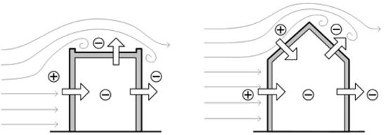
Wind forces act on all buildings, typically creating a positive pressure on the windward face and negative (suction) pressures on the walls. Bernoulli's equation can be used to calculate the pressure imposed on a building as function of wind speed. The stagnation pressure is defined as the pressure exerted by a flow decelerated to zero speed, and is given by:
Pstag = 1/2. r . V2 @ 0.65 · V2 [1]
where r is the air density [kg/m3], approximately 1.3 kg/m3 at 0 C
and
V the wind velocity [m/s]
The pressure calculated from Equation 1 is not directly what is imposed on a building, and so a pressure coefficient is introduced to modify the stagnation pressure as:
P = Cp · Pstag [2]
This pressure coefficient can be found for simple buildings in numerous references and ranges from a typical value of Cp = 0.7 to 0.8 on the windward side to Cp = -0.3 to -0.5 on the leeward. Local pressure coefficients around parapets, under glancing wind directions, and other turbulent flow conditions are often much larger, e.g., Cp = +3 to -5. Interior pressure coefficients range from -0.3 to -1.0, and the arithmetic sum is the net pressure acting across the enclosure. A concise summary of typical pressure coefficients can be found in Chapter 14 of the ASHRAE Handbook of Fundamentals [ASHRAE 1997].

Figure 1: Forces Driving Air Flow through Building Enclosures
Low-slope roofs tend to have mostly negative (uplift) pressures, especially on the leading edge (Figure 2). Roofs with slopes above about 25 degrees experience positive pressures on the windward face, and suctions on the leeward.
Figure 2: Wind Pressure Effects on Representative Buildings
Stack Effect
Stack effect pressures are generated by differences in air density with temperature, i.e. hot air rises and cold air sinks. The air within a building during the wintertime acts like a bubble of hot air in a sea of cold air. In the summertime the situation is reversed, although air temperature differences are usually less.
The density of dry air, ra, varies with temperature. The greater the height of a column of air, the greater the potential difference in pressure if that column is at a different temperature. The pressure difference generated by a column of air h meters high with temperature difference between indoor and outdoor air at standard temperature and pressure is approximately:

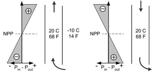
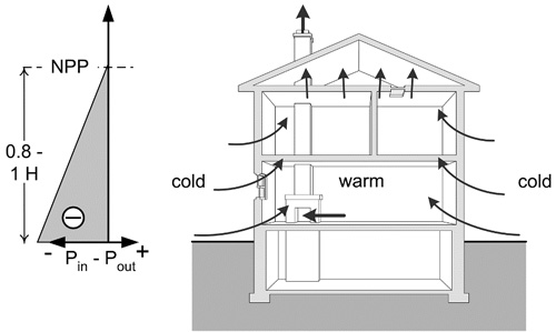
For example, if the air in a one meter high cylinder, open at the bottom and containing room temperature air (20 °C) is taken into the outdoors at a temperature of -10 °C, an outward pressure of 1.34 Pa would act at the top (Figure 3). The pressure at the bottom must be zero since it is connected to the outdoors. The horizontal plane at which the pressure equals the outdoor pressure (i.e. the difference is zero) is called the Neutral Pressure Plane (NPP).
Figure 3: Pressure in Open-Ended Cylinder Due to Buoyancy
If the cylinder remained outdoors, the air it contained would slowly cool down to the exterior temperature and no pressure difference would exist. If the cylinder were then inverted and brought back indoors, the pressure at the closed end of the cylinder would again be 1.34 Pa acting outward as the cold air fell downward relative to the indoor air.
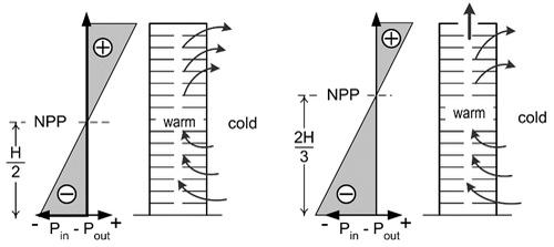
In the above examples, no flow occurred because no flow path was provided. If an open-ended cylinder containing room temperature air where used, any temperature difference between the cylinder and the surrounding air would cause flow, and the warm air would be immediately removed and replaced with cool outdoor air. However, if a heating coil were added to the cylinder to maintain the air temperature at 20 °C, airflow in the bottom would be heated. This is analogous to a heated building. Friction would slow air flow and result in a constant pressure drop along the height of the cylinder. Note that the NPP would now be located at mid-height and that air flow is involved (Figure 4). Obviously, the less air flowing through this cylinder the less heat energy required to maintain the interior of the cylinder at 20 °C.
Figure 4: Flow through a heated or cooling cylinder or building
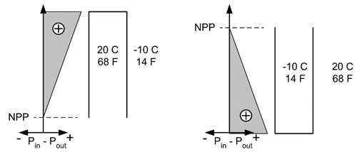
(Left) Floors leakier than walls: building acts like a perforated tub
(Right) Top leakier than bottom: NPP rise
Figure 5: Stack Effect in Real Buildings
Although houses tend to be only 3 to 9 m (9 to 27 feet) tall, stack effect can be a major force driving airflow, particularly in climates with a large temperature difference (more than 25 °C / 40 °F) across the enclosure. Often the exhaust of chimneys and fans, as well as leaky ceiling planes result in a Neutral Pressure Plane located near the ceiling level (Figure 6).
Figure 6: Stack effect during cold weather in a house
In warm climates and during warm weather, stack effect reverses and air is often drawn in at the top and pushed out at the bottom. Infiltration of warm moist air in warm weather can cause as many problems as exfiltration of warm moist air in the winter.
Mechanical Equipment
Fans and blowers cause the movement of air within buildings and through enclosures. By doing so, they can generate large pressures. If more air is exhausted from a building than is supplied, a net negative pressure is generated and vice versa.
If air is forced through the ducts that leave the building enclosure or pass outside the primary air barrier system (e.g., the very bad practise of placing ductwork in vented attics or crawlspaces) any leaks in the ductwork (and all ducts have some leakage, most ductwork is very leaky) will result in a net exhaust of air, and hence a net negative inward pressures on the building enclosure. The reverse can happen if leaky ducts outside the air barrier are under a net suction pressure.
Bathroom exhaust fans, clothes dryers, built-in vacuum cleaners, dust collection systems, and range hoods all exhaust air from a building. This creates a negative pressure inside the building. If the enclosure is airtight or the exhaust flow rate high, large negative pressures can be generated. These negative pressures have the potential to cause several problems:
- by driving inward air leakage through the enclosure, outdoor air may transport moisture into the enclosure during hot humid outdoor weather conditions
- the negative pressures can cause backdrafting of combustion appliances.
- the efficiency of most air handling devices will decrease with increasing back pressures.
Commercial HVAC systems both supply and extract air from buildings. This means both positive and negative pressure can be developed, depending on the balance of supply to exhaust flows. Dust collection systems, commercial range hoods and other industrial air handlers can move thousands of liters per second, seriously disturbing the pressure-flow relationship within a building and should be handled on an individual basis.
In design, one should aim for almost no mechanically-induced air pressure across the enclosure. This is achieved by balancing systems so that the same amount of air is supplied as is exhausted. In some case pressurization can be used to control airflow direction — buildings that are depressurised in winter will not have air leakage condensation problems, buildings that are pressurized may have winter condensation problems (if the enclosure leaks) but will exclude pollution from, for example, a parking garage.
Controlling Air Flow Through Enclosures
Controlling the flow of air across the enclosure, e.g., from the interior to the exterior or vice versa, is the most important aspect of air flow control. While no building is perfect, the goal of a design should be near zero flow and
The primary plane of air flow control in a wall is generally called the air barrier. Because such a plane is in practise comprised of elements and joints, the term air barrier system (ABS) is preferred. In framed, low-rise residential buildings, the primary air barrier system is often comprised of an inner layer of drywall (sealed around the perimeter and at all penetrations) or sealed polyethylene. However, outer layers of sheathing, (such as gypsum, waferboard, fiberboard, EXPS) and housewrap or building paper provide additional resistance to out-of-plane air flow through the enclosure assembly. In many modern building assemblies, exterior sheathing is designed and detailed to be part of an outboard air barrier system. Note that the plane of airtightness labelled by the designer (and all building sections should indicate what is intended to be the air barrier) or builder as the air barrier system may not in fact act as the ABS.
Basic Requirements of Air Barrier Systems
Typically, several different materials, joints and assemblies are combined to provide an uninterrupted plane of primary airflow control. Regardless of how air control is achieved, the following five requirements must be met by the air barrier system (ABS):
Continuity. This is the most important and most difficult requirement. Enclosures are 3-D systems! ABS continuity must be ensured through doors, windows, penetrations, around corners, at floor lines, soffits, etc.
Strength. If the ABS is, as designed, much less air permeable than the remainder of the enclosure assembly, then it must also be designed to transfer the full design wind load (e.g., the 1-in-30 year gust) to the structural system. Fastenings can often be critical, especially for flexible non-adhered membrane systems.
Durability. The ABS must continue to perform for its service life. Therefore, the ease of repair and replacement, the imposed stresses and material resistance to movement, fatigue, temperature, etc. are all considerations.
Stiffness. The stiffness of the ABS (including fastening methods) must reduce or eliminate deflections to control air movement into the enclosure by pumping. The ABS must also be stiff enough that deformations do not change the air permeance (e.g., by stretching holes around fasteners) and/or distribute loads through unintentional load paths.
Impermeability. Naturally, the ABS must be impermeable to air. Typical recommended air permeability values are less than about 1.3 x 10⁻⁶ m3/m2/Pa. However air barrier materials are commonly defined as materials which pass less than Q 0.02 lps/m2 @75 Pa. Although this is an easy property to measure it is not as important as might be thought. In practise, the ability to achieve other requirements (especially continuity) are more important to performance, and the air “permeance” of joints, cracks, and penetrations outweighs the air permeance of the solid materials that make up most of the area of the ABS. Hence, a component should have an air leakage rate of less than Q 0.2 lps/m2 @75 Pa, and the whole building system should leak less than Q 2.0 lps/m2 @75 Pa.
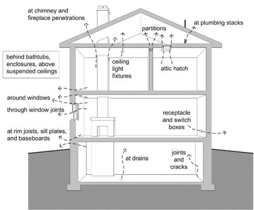
Figure 7: Typical air leakage paths.
As noted earlier, the secondary planes of air flow resistance fulfill several functions, either on their own or in conjunction with the other planes of air flow resistance. These secondary barriers not only add marginally to the overall airflow resistance of the assembly, they provide a level of redundancy if the primary air barrier is designed, built, or performs imperfectly. If the secondary barrier is of sufficient air tightness it may provide a great improvement to overall airtightness so long as compartmentalisation is provided. For example, research has shown that housewraps, sometimes called air infiltration retarders, can significantly reduce airflow through an imperfect primary air barrier even if they are not designed or built as an ABS. The satisfactory performance of many older wall systems can often be explained by the unintentional, and often synergistic, contribution to airtightness that layers such as building paper, board and panel sheathing, brickwork, etc.
Air Barrier Systems vs Vapor Barriers
The fact that many vapor barriers also retard or eliminate air flow sometimes causes confusion. In fact, much of the older literature (and a disappointing proportion of current documents) confuse or combine the function of the ABS and vapor barriers, and the difference between the two is still one of the most common building science questions. Hence, the distinction will be presented here once again.
The function of a vapor barrier is simply the control of water vapor diffusion to reduce the occurrence or intensity of condensation. As such, it has one performance requirement: it must have the specified level of vapor permeance and be installed to cover most of the area of an enclosure.
Many codes require the use of a vapor barrier in all enclosures. Some codes wisely require that vapor diffusion be controlled when an assembly “would be adversely affected by condensation.” The need for a specific vapor barrier layer can be assessed by simple calculations, and rarely is a layer with very low permeance like polyethylene sheet justified. The 2009 IRC, IBC, and IEC will all have tables outlining science-based requirements for vapor barriers. They usually do not require the use of a very low permeance polyethylene as an air barrier or a vapor barrier. See also BSD -106 Understanding Vapor Barriers for more information.
Air barrier systems control air flow and thereby control convective vapor flow. As can be seen from the previous sections, the control of air flow provides other benefits and has at least five performance requirements to meet.
Canadian building codes require an air barrier system in all enclosures that would be adversely affected by condensation. In practise, this means air barriers are required for almost all conceivable types of building enclosures, especially since they provide more than just control of condensation. Some states (e.g., Massachusetts commercial code) and agencies (e.g., Army Corp of Engineers, General Services Administration) are beginning to mandate air barrier systems and enforce airtightness standards.
The vapor permeance of the air barrier must be considered in the same way as all other materials in an assembly should be. For example, in cold climates, a vapor barrier on the exterior is usually not acceptable (but can be designed for, as it is in an exposed membrane low-slope roof or a wall with metal cladding), whereas in hot humid climates, this location would be desirable. But the vapor permeance of the ABS is no more important than the vapor permeance of any other materials in an assembly, such as the cladding, sheathing, insulation, interior finish, etc.
Common Air Barrier Systems
A sheet of 6 mille (0.15 mm) thick polyethylene is often used as a vapor barrier in very cold climates (Zones 6 and 7). Poly is cheap to buy and install and has very low vapor permeance. However, it fails or barely meets most air barrier requirements other than air impermeability. It is difficult and relatively expensive to achieve continuity, especially since it is pierced by services and enclosure penetrations at many locations. It is likely to fail structurally when exposed to wind gust loads, and can fail through fatigue if it flaps because of varying wind pressures. Hence, it is not very durable. It is so flexible that it can deform and transfer loads through unexpected paths, deform batt insulation, tear fastenings, pump air, etc. Nevertheless, for undemanding applications such as low-rise housing, poly may act as both the vapor barrier and the air barrier. Poly on the interior should not be used in air conditioned buildings in Zones 5 or lower as its low vapor permeance poses an unacceptable risk of interstitial condensation during warm weather.
The airtight drywall approach (ADA) employs the interior layer of painted drywall as part of the ABS and poly, vinyl wall paper, or an appropriate type of paint as the vapor control layer. The drywall is stiff and strong enough for most applications and because it is visible, it is easy to inspect, repair, and to ensure continuity. Difficulty in achieving continuity is often encountered at service penetrations, wall-floor interfaces, intersection walls, transitions, partition walls, etc. Despite these difficulties, with a little care and training the ADA air barrier system is often quite successful and can be used in a wide-range of steel and wood framed roof and wall systems in both residential and commercial construction.
The vapor barrier and air barrier are often separated in enclosures employing housewraps or exterior sheathing (e.g., well sealed exterior gypsum, plywood, or OSB) as the primary air barrier. Poly, foil-backed drywall (in very cold climates), or paint is installed near the interior and acts as the vapor barrier. The advantage of such exterior air barriers is that they are often easier to install in such a manner as to span over all of the many interior service penetrations, plumbing, structural components, etc.
Another approach to exterior air barriers is the use of air impermeable, usually foam plastic or foil-faced, rigid insulation boards with sheathing tape and/or gaskets at joints. Such systems have the advantage of fewer penetrations, but the disadvantage that they are difficult to inspect and repair. The ability of these systems, including their joints, to transfer wind loads through connectors to the structural frame must be investigated for each application.
Spray foam, open-celled or closed-cell can be used as a very effective part of an air barrier system. When applied to the exterior of blockwork or sheathing, they form a continuous fully-adhered system. Transitions, movement joints, and penetrations require careful detailing to ensure airtightness. When the foam is sprayed within a stud cavity, much more effort is required to seal the joint between the floor sheathing and bottom plate, top plate to rim joist (often spray foam), etc.
Reinforced concrete is usually sufficiently airtight to form part of an ABS so long as the concrete is dense and crack size and spacing are controlled by the appropriate use of reinforcing (standard spacings used in reinforced concrete design are sufficient). Blockwork is not generally sufficiently impermeable to act as an air barrier. Small shrinkage cracks further compromise its airtightness. The application of a thick layer of block paint, or a thin layer of parging, preferably with fibres to limit crack sizes, renders blockwork walls airtight.
In commercial applications, bitumen-based air barriers, in either liquid or reinforced membrane form, are often adhered to the exterior of blockwork, concrete, or exterior gypsum sheathing. To ensure continuity, compatible membranes are used to bridge cracks and tie the ABS to windows, etc. This type of air barrier tends to be very vapor impermeable and so also acts as a vapor barrier. Therefore, the majority of the insulation must be applied outside of such an ABS in cold climates.
Polymer-modified and fibre-reinforced thin plasters are also available as air barriers. These systems require flexible joint details around penetrations, but are non-combustible and may be as vapor permeable or impermeable as specified. A variety of heavy-duty elastomeric liquid-applied air barrier membranes are also available. These products can have a range of vapor permeance values (from very impermeable to very permeable). With the appropriate analysis, they can be placed anywhere in an enclosure and used in all climates.
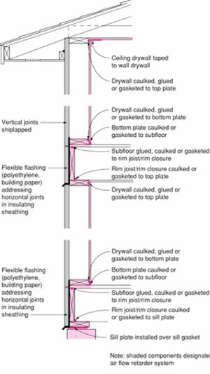
In framed systems, two air barrier systems, one inside and one outside of the framing, are often desirable, with framing members consciously designed as in-plane compartment separators to resist the internal lateral flows generated by wind pressures (Figure 8). Such redundancy is needed because of the susceptibility of these systems to wind washing, ABS failure, convective loops, and other airflow control problems.
Figure 8: Airtight Drywall Approach applied to a wood-framed enclosure
Figure 9: Housewrap air barrier system
Figure 10: Polyethylene air barrier system (very cold climates only—Zones 6 or higher)
Figure 11: Exterior sheathing (insulated or not) air barrier system
Conclusions
Air flow control is important for several reasons: to control moisture damage, reduce energy losses, and to ensure occupant comfort and health. Airflow across the building enclosure is driven by wind pressures, stack effect, and mechanical air handling equipment like fans and furnaces. A continuous, strong, stiff, durable and air impermeable air barrier system is required between the exterior and conditions space to control airflow driven by these forces.
Air barrier systems should be clearly shown and labelled on all drawings, with continuity demonstrated at all penetrations, transitions, and intersections. In addition, enclosure assemblies and buildings should be vertically and horizontally compartmentalized, may require secondary planes of airtightness (such as those provided by housewraps and sealed rigid sheathing) and may need appropriately air impermeable insulations or insulated sheathing.
It must be noted that increased airtightness must be matched by an appropriate ventilation system to dilute pollutants, provide fresh air, and control cold weather humidity levels. Good airflow control through and within the building enclosure will bring many benefits: reduce moisture damage, energy savings, and increased health and comfort. However, while airflow usually causes wetting in enclosures, it also can be a powerful drying mechanism. Therefore, enclosures with increased air flow control demand greater attention to other sources of drying (diffusion is the only practical mechanism available) and the reduction or elimination of other sources of wetting (built-in, rain and diffusion).
References
Brook, M.S., "Rationalizing Wall Performance Criteria", Proc. Sixth Conference on Building Science &Technology, Toronto, March 5-6, 1992, pp.145-161.
Brown, W.C., Bomberg, M.T., Ullet, J.M. and Rasmussen, J. "Measured Thermal Resistance of Frame Walls with Defects in the Installation of Mineral Fibre Insulation", J. of Thermal Insulation and Building Envelopes, Vol 16, April 1993, pp. 318-339.
Controlling Stack Pressure in High-Rise Buildings by Compartmenting the Building. Research Report for CMHC, March, 1996.
Garden,G.K., Control of Air Leakage is Important. Canadian Building Digest 72, National Research Council of Canada, Ottawa, 1965.
Lecompte, J., "Influence of Natural Convection in an Insulated Cacity on the Thermal Performance of a Wall", Insulation Materials, Testing and Applications, ASTM STP1030. D.L. McElry and J.F. Kimpflen, Eds., Amercian Society for Tesitng and Materials, Philadelphia, 1990, pp. 397-420.
Lstiburek, Joseph and Carmody, John. Moisture control handbook : principles and practices for residential and small commercial buildings. New York : Van Nostrand Reinhold, 1993.
Ojanen, T. and Kohonen, R.,"Hygrothermal Performance Analysis of Wind Barrier Structures", ASHRAE Transactions, Symposia, Chicago, 1995, pp. 595-606.
Straube, J.F., Burnett, E.F.P.,"Rain Control and Screened Wall Systems", Proc. Seventh Conference on Building Science &Technology, Toronto, March, 1997, pp.18-37.
Timusk, J. and Lischkoff, J., Moisture and Thermal Aspects of Insulated Sheathings", Proc. Second Conference on Building Science &Technology, London, Ont., 1983, pp.71-91.
Uvsløkk, S., "The Importance of Wind Barriers for Insulated Wood Frame Constructions," Proc. of Symposium and Day of Building Physics, Lund University, August 24-27, 1987, Swedish Council for Building Research, 1988, pp. 262-267 and Uvslokk, S.,1996, "The importance of wind barriers for insulated timber frame construction", J. Thermal Insul. and Bldg. Envs., V.20, July, p.40-62.
Wilson, A.G., "Air Leakage in Buildings", Canadian Building Digest 23, National Research Council of Canada, Ottawa, Dec 1963.

