Controlling heat flow, airflow, moisture flow and solar and other radiation will control the interactions among the physical elements of the building, its occupants and the environment. Of these four, airflow “merits major consideration mainly because of its influence on heat and moisture flow” (Hutcheon, 1953). Airflow carries moisture that impacts a materials long-term performance (serviceability) and structural integrity (durability). Airflow also affects building behavior in a fire (spread of smoke and other toxic gases, supply of oxygen), indoor air quality (distribution of pollutants and location of microbial reservoirs) and thermal energy use. One of the key strategies in the control of airflow is the use of air barriers.
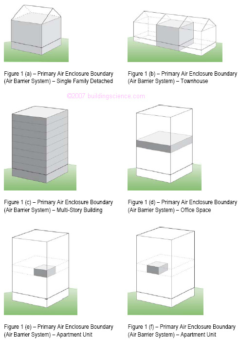
Air barriers are systems of materials designed and constructed to control airflow between a conditioned space and an unconditioned space. The air barrier system is the primary air enclosure boundary that separates indoor (conditioned) air and outdoor (unconditioned) air. In multi-unit/townhouse/apartment construction the air barrier system also separates the conditioned air from any given unit and adjacent units. Air barrier systems also typically define the location of the pressure boundary of the building enclosure.
In multi-unit/townhouse/apartment construction the air barrier system is also the fire barrier and smoke barrier in inter-unit separations. The inter-unit separation must also meet the specific fire-resistance rating requirement for the given separation.
The air barrier system also separates garages from conditioned spaces. In this regard the air barrier system is also the “gas barrier” and provides the gas-tight separation between a garage and the remainder of the house or building.
Typical configurations of air barrier system enclosures are illustrated in Figure 1.
Approaches
Air barriers are intended to resist the air pressure differences that act on them. Rigid materials such as gypsum board, exterior sheathing materials like plywood or OSB, and supported flexible barriers are typically effective air barrier systems if joints and seams are sealed. Spray foam systems can also act as effective air barrier systems either externally applied over structural elements or internally applied within cavity systems.
Air barrier systems keep outside air out of the building enclosure or inside air out of the building enclosure depending on climate or configuration. Sometimes, air barrier systems do both.
Air barrier systems can be located anywhere in the building enclosure – at the exterior surface, the interior surface, or at any location in between. In cold climates, interior air barrier systems control the exfiltration of interior, often moisture-laden air. Whereas exterior air barrier systems control the infiltration of exterior air and prevent wind-washing through cavity insulation systems.
Air barrier systems should be:
impermeable to air flow;
continuous over the entire building enclosure or continuous over the enclosure of any given unit;
able to withstand the forces that may act on them during and after construction;
durable over the expected lifetime of the building.
Numerous approaches can be used to provide air barrier systems in buildings. Some of the more common are:
exterior air barrier system using self-adhered modified bituminous membrane sheets (Figure 2, Photograph 1, Photograph 2);
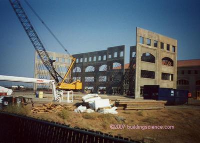
exterior air barrier system using precast, site-cast or tilt-up concrete panels (Figure 3, Photograph 3);
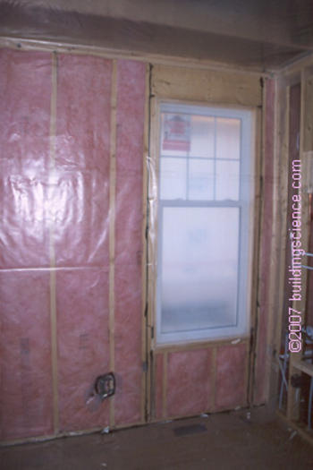
interior air barrier system using gypsum board (Figure 4, Figure 5, Figure 6, Figure 7, Photograph 4);
interior air barrier system using sheet polyethylene (Figure 8, Photograph 5).
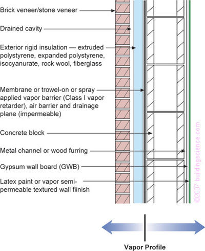
Figure 2: Exterior Air Barrier Using Adhered Membrane
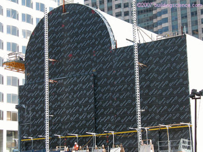
Photograph 1: Exterior Air Barrier Using Adhered Membrane
(Note the air barrier continuity where the wall meets the roof)
Photograph 2: Exterior Air Barrier Using Adhered Membrane
(Note the rigid insulation installed on the exterior of the air barrier system)
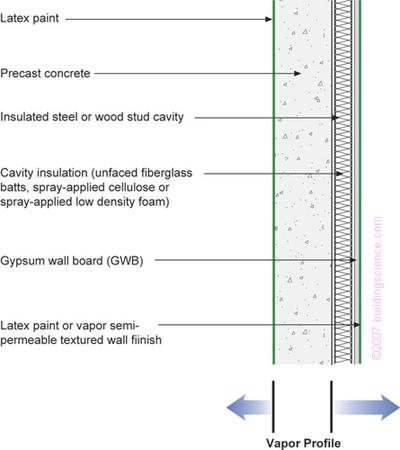
Figure 3: Exterior Air Barrier Using Precast/Site Cast Concrete
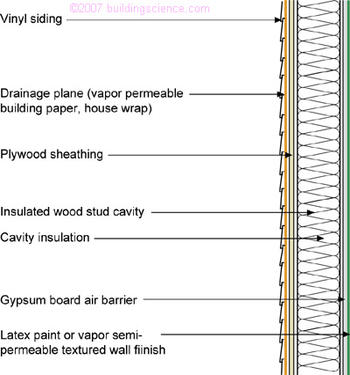
Figure 4: Interior Air Barrier Using Gypsum Board
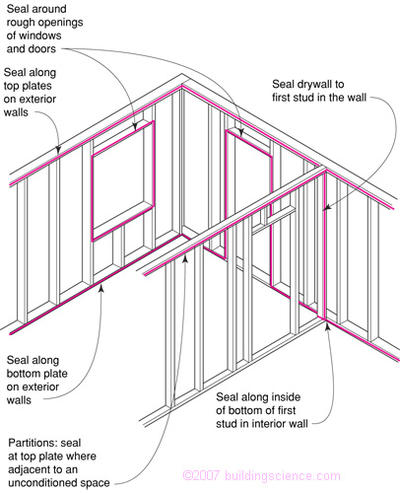
Figure 5: Interior Air Barrier Using Gypsum Board – Openings
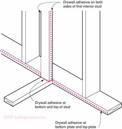
Figure 6: Interior Air Barrier Using Gypsum Board – Intersecting Walls
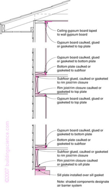
Figure 7: Interior Air Barrier Using Gypsum Board – Section
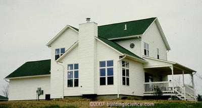
Photograph 4: Typical Residential Enclosure With Interior Air Barrier
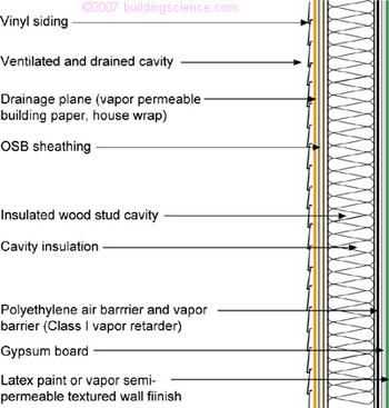
Figure 8: Interior Air Barrier Using Polyethylene Sheet
Spray applied foam insulations can be used as interstitial (cavity) air barrier systems. Damp spray applied cellulose does not meet the performance requirements of air barrier materials or assemblies – it is an air retarder.
Air barrier systems also “compartmentalize” buildings (Figure 1 (b), Figure 1 (d), Figure 1 (e) and Figure 1 (f)). These interior air barrier assemblies are typically fire-stopped and fire-taped gypsum board (Photograph 6).
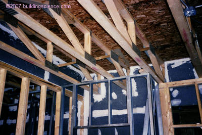
Photograph 6: Interior Multi-Unit Compartmentalization
(Note the sealing of the interior wall assembly to the underside of the floor system)
The significant advantage of exterior air barrier systems is the ease of installation and the lack of detailing issues related to intersecting partition walls and service penetrations.
An additional advantage of exterior air barrier systems is the control of wind-washing that an exterior air seal provides with insulted cavity frame assemblies.
The significant disadvantage of exterior air barrier systems is their inability to control the entry of air-transported moisture into insulated cavities from the interior. As a result most exterior air barrier systems are insulated on their exterior side with rigid or semi-rigid insulations that are not sensitive to wind-washing.
An advantage of interior air barrier systems over exterior systems is that they control the entry of interior moisture-laden air into insulated assembly cavities during heating periods. The significant disadvantage of interior air barrier systems is their inability to control wind-washing through cavity insulation and their inability to address the entry of exterior hot-humid air into insulated cavities in hot-humid climates.
Installing both interior and exterior air barrier systems can address the weakness of each.
Air barrier materials can also be provided with properties which also class them as vapor barriers. An example of this are self-adhered modified bituminous membranes and sheet polyethylene which can be used as both an air barrier and a vapor barrier.
Keep in mind however, sheet polyethylene on the inside of building assemblies in cold, mixed-humid, marine, hot-dry and hot-humid climates is not generally a good idea; drying of building assemblies in these climates occurs to the inside as well as to the outside.
Interior drying is typically necessary in air-conditioned enclosures. In other words, interior vapor barriers such as polyethylene and vinyl wall coverings should never be installed in air-conditioned buildings – even ones located in cold climates.
Performance Requirements
Air barrier systems typically are assembled from materials incorporated in assemblies that are interconnected to create enclosures. Each of these three elements has measurable resistance to airflow. The recommended minimum resistances or air permeances for the three components are listed as follows:
- Material 0.02 l/(s-m2)@75 Pa
- Assembly 0.20 l/(s-m2)@75 Pa
- Enclosure 2.00 l/(s-m2)@75 Pa
Materials and assemblies that meet these performance requirements are said to be air barrier materials and air barrier assemblies. Air barrier materials incorporated in air barrier assemblies that in turn are interconnected to create enclosures are called air barrier systems.
Materials and assemblies that do not meet these performance requirements, but are nevertheless designed and constructed to control airflow are said to be air retarders.
The recommended minimum resistances are based on experience and current practice:
Gypsum board is a common air barrier material and it readily meets the material air permeance recommendation (0.0196 l/(s-m2@ 75 Pa) (Bumbaru, 1988).
The National Building Code of Canada specifies that the principle air barrier material may have a maximum air permeance of 0.02 l/(s-m2)@75 Pa.
The U.S. Department of Energy Building America Program sets an enclosure air permeance requirement of 1.65 l/(s-m2)@75 Pa for residential buildings.
ASTM E-1677-00 Standard Specification for an Air Retarder (AR) Material or System for Low-Rise Framed Building Walls currently calls for an assembly air permeance requirement of 0.30 l/(s-m2)@75 Pa.
Painted masonry block walls have an estimated air permeance of less than 0.20 l/(s-m2)@ 75 Pa (Tamura and Shaw, 1976 (a) and (b) and Hutcheon, N.B., and Handegord, G.O., 1983).
Most buildings that are correctly fire stopped without gross defects such as open soffits meet the enclosure air permeance recommendation (as tested by the author).
The Building Services Research and Information Association (BSRIA) of Great Britain recommends 1.8 l/(s-m2)@75 Pa as “best practice” for the air permeance of residential building enclosures.
Verification and Testing
Material specifications and assembly specifications are typically verified in laboratory settings using available standards (ASTM E 2178–03 Standard Test Method for Air Permeance of Building Materials for material air permeance and ASTM E 283-04 Standard Test Method for Determining Rate of Air Leakage Through Exterior Windows, Curtain Walls, and Doors Under Specified Pressure Differences Across the Specimen for assembly air permeance).
Enclosure specification of air permeance can only be verified in the field. Two verification approaches can be used:
Using a portable fan to induce a pressure difference in a building enclosure or in a building compartment (ASTM E 779-03 Standard Test Method for Determining Air Leakage Rate by Fan Pressurization Method).
Using a buildings HVAC system to induce a pressure difference (CAN/CGSB-149.15-96, Determination of the Overall Envelope Airtightness of Buildings by the Fan Pressurization Method Using the Building’s Air-Handling Systems).
The first approach is used for relatively small enclosures and compartments. The second approach is used for large building enclosures such as described in Figure 1 (c).
Both approaches involve creating an air pressure difference using a known airflow rate. Photograph 7 shows the use of a portable fan to extract air from an enclosure or compartment creating a pressure difference. Applying a simple mass balance and a power law relationship yields the familiar leakage curve (Figure 9, Figure 10 and Figure 11). Normalizing provides air permeance values for the enclosure or compartment.
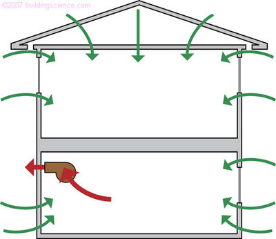
Figure 9: Enclosure Mass Balance
(Mass flow rate out equals mass flow rate in)

Figure 10: Power Law Relationship
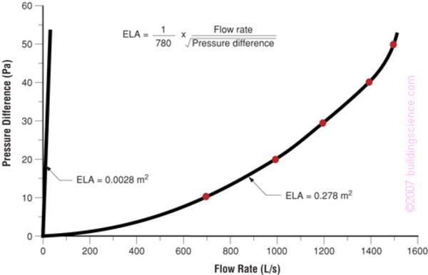
Figure 11: Typical Enclosure Flow vs Pressure Curve
The air permeance of the building enclosure for the large facility shown in Photograph 8 was determined using the second approach. The buildings internal fans were configured as per CAN/CGSB-149.15-96 (Figure 12) to create a series of air pressure differences that were measured using a multi-channel digital manometer (Photograph 9 and Figure 13). A CONTAM model (Walton, 1997) representative of the building was created and the air permeance values of the model were adjusted until the air pressure response of the model matched the measured air pressure response of the building (Figure 14 and Figure 15).
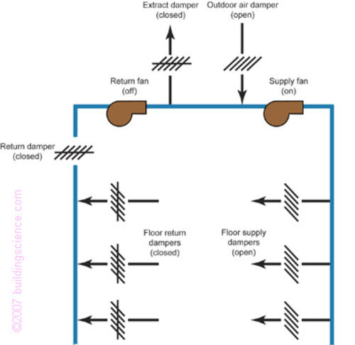
Figure 12: Pressurization Using Buildings Internal Fans
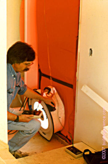
Photograph 7: Portable Pressurization Fan ("blower door" test apparatus)

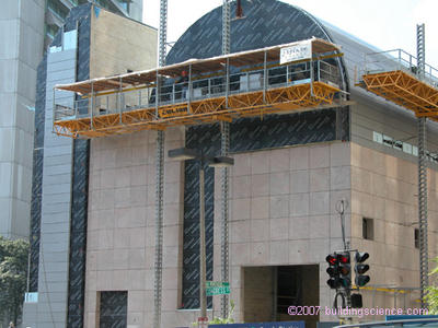
Photograph 8: Large Facility Testing - “Blower Door” approach on steroids
(Facilities internal fans used to create pressure difference)

Photograph 9: Multi-Channel Digital Manometer
(Interior to exterior and inter-zonal pressures are measured)
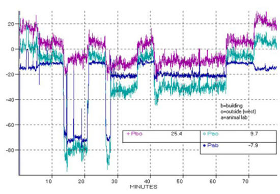
Figure 13: Measured Pressure Response of Facility
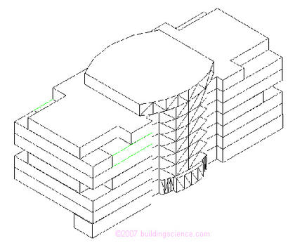
Figure 14: CONTAM Model of Facility
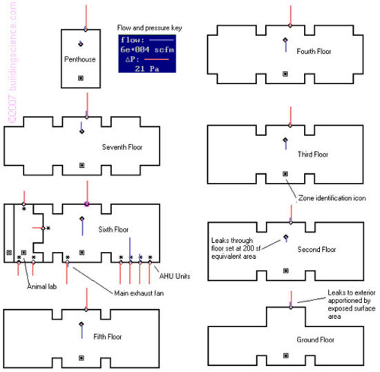
Figure 15: CONTAM Model of Facility
(Air permeance values of the model are adjusted until the air pressure response of
the model matches the measured air pressure response of the facility)

Table 1: Air Permeance Conversions for Materials, Assemblies and Enclosures
Conclusion
In order to design and build safe, healthy, durable, comfortable and economical buildings airflow must be controlled. Airflow carries moisture that impacts a materials long-term performance (serviceability) and structural integrity (durability), behavior in fire (spread of smoke), indoor air quality (distribution of pollutants and location of microbial reservoirs) and thermal energy. One of the key strategies in the control of airflow is the use of air barriers.
Understanding air barriers is necessary in order to develop effective enclosure design, set achievable performance requirements and verify compliance.
References
ASTM E 283-04 Standard Test Method for Determining Rate of Air Leakage Through Exterior Windows, Curtain Walls, and Doors Under Specified Pressure Differences Across the Specimen for assemblies, West Conshohocken, PA, American Society For Testing and Materials
ASTM E 779-03 Standard Test Method for Determining Air Leakage Rate by Fan Pressurization Method, West Conshohocken, PA, American Society For Testing and Materials
ASTM E-1677-00 Standard Specification for an Air Retarder (AR) Material or System for Low-Rise Framed Building Walls, West Conshohocken, PA, American Society For Testing and Materials
ASTM E 2178 – 03 Standard Test Method for Air Permeance of Building Materials, West Conshohocken, PA, American Society For Testing and Materials
BSRIA, Airtightness Testing: A Guide For Clients and Contractors, ISBN 0-86022-592-5, October 2001
Bumbaru, D., Jutras, R., and Patenaude, A.; Air Permeance of Building Materials, Canada Mortgage and Housing Corporation, Ottawa, Canada, June 1988
CAN/CGSB-149.15-96, Determination of the Overall Envelope Airtightness of Buildings by the Fan Pressurization Method Using the Building’s Air-Handling Systems, Ottawa, Canadian General Standards Board, as modified by Amendment No. 1, April 1999, Canadian General Standards Board, Ottawa, Canada
Hutcheon, N.B.; "Fundamental Considerations in the Design of Exterior Walls for Buildings, " Engineering Journal, Vol. 36, No. 1, pp. 687-698, June, 1953.
Hutcheon, N.B., and Handegord, G.O.; Building Science for a Cold Climate, Table 11.4, page 284, ISBN 0-9694366-0-2, National Research Council of Canada, Ottawa, 1983
Tamura, G.T., and Shaw, C.Y.; "Studies on Exterior Wall Tightness and Air Infiltration of Tall Buildings," ASHRAE Transactions 82(Part I): 122-134; (NRCC 15732); Atlanta, GA, 1976
Tamura, G.T., and Shaw, C.Y.; "Air Leakage Data for the Design of Elevator and Stair Shaft Pressurization Systems," ASHRAE Transactions 82(Part II): 179-190; Atlanta, GA, 1976
Walton, G.N.; CONTAM96, NISTIR 6056, U.S. Department of Commerce, National Institute of Standards and Technology, Building and Fire Research Laboratory, Gaithersburg, MD, September, 1997.