Adhered veneers, in which masonry units are directly attached to a substrate via mortar and ties without a drainage or ventilation gap, have become a very popular finish in residential and light commercial construction. Typical applications apply masonry over a bed of lath-reinforced mortar over a drainage plane (often of building paper or felt). When used over wood- or steel-framed walls, numerous reports of moisture problems and failures have been received.
Introduction
Adhered veneers, in which masonry units are directly attached to a substrate via mortar and ties without a drainage or ventilation gap, have become a very popular finish in residential and light commercial construction. Typical applications apply thin masonry units over a bed of lath-reinforced mortar over a drainage plane (often a single layer of building paper, felt, or housewrap).
When used over wood- or steel-framed walls, numerous reports of moisture problems and failures have been reported (Rymell 2007). The lack of a well-defined drainage space, and warm-weather inward vapor drives have been implicated as the reasons for these moisture problems.
Drainage can easily be provided by installing a second layer of building paper, particularly if one layer is a creped housewrap, and ensuring that flashing and weep holes are included. However, controlling inward vapor drives is more problematic, as building papers and housewraps are highly vapor permeable, and both the mortar and the masonry unit can store a significant amount of rain water via capillary absorption. During sunny weather following rain, water vapor stored in the masonry can be driven into the sheathing and into the stud bay, resulting in wood decay and condensation on air-conditioned interior surfaces. Air-conditioned buildings with low-permeance vapor retarders (such as polyethylene, vinyl wall paper, and aluminum foil) exacerbate this problem.
One proposed solution to avoiding the risk of these problems is the use of a vapor-impermeable air gap membrane behind the adhered veneer. A rigid plastic membrane will control inward vapor drives, but will not allow water vapor in the studspace or framing to dry to the exterior. Previous research suggests that a ventilated air space may allow the required drying (Karagiozis et al 2005, Straube et al 2004), but this has not been demonstrated in the field for an impermeable air gap membrane.
Experimental Program
An experimental program was developed to measure and compare the performance of adhered veneer cladding side-by-side with an alternative method that uses a vapour-impermeable rigid polymer-based air-gap membrane. The objective of the study was to compare adhered veneer walls using a rigid plastic dimple sheet in place of asphalt impregnated paper as the sheathing membrane. These walls were installed in a natural exposure field testing facility in Waterloo, Ontario, Canada.
To collect field measurements for over a year of monitoring two types of wood-framed walls, one with an air gap membrane and another installed following standard practice. No penetrations through the test assembly were installed to eliminate the potential of bulk rain penetration problems. Each type of wall was faced either north or south in a test hut located in Water Ontario. Waterloo has an average of approximately 4300 Celsius heating degree days (7800 HDD F).
The hut is in an exposed location, free from obstruction by other buildings.
All of the test panels were 8 ft (2.4 m) in height, and 4 ft (1.2 m) in width and shared construction of 2x6 wood framing on approximately 16” (0.4 m) centers with OSB sheathing, a poly interior vapor barrier, drywall finish and air barrier, and R19 (RSI3.5) fiberglass batt insulation.
Instrumentation included a temperature and relative humidity sensor in the drain space, as well as the stud space, moisture content sensors in the sheathing and framing, and temperature sensors on the cladding and drywall. All of the monitored framing is clear eastern white pine (EWP), and the remaining framing is generic SPF framing. Details of the instrumentation, data conversion and other details can be found in Straube et al (2002). The data was measured at 5 minute intervals and the average recorded on an hourly basis. The sensor layout is shown in Figure 1.
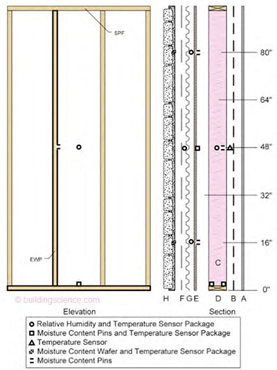
Figure 1: Typical Wall Construction and Sensor Layout For Full Scale Wall Testing
The opening in the test facility was lined with a wood frame wrapped in a self-adhered flashing to help isolate the test panel from any other moisture sources. All of the instrumentation is located in the centre third of the wall over the entire height. This helps minimize edge effects and simulates accurate field performance of the enclosure system.
Moisture content behind the cladding was measured using a moisture content wafer. These sensors consist of a small piece of wood, of a known species, with moisture content pins installed into it (Ueno et al, 2008). The sensor equilibriates with the liquid or vapor around it, but because of its hygric mass, it does not react quickly. This sensor is generally used in locations where the moisture content is required, and the moisture content does not change quickly, such as masonry work.
Monitoring began on July 16, 2007 and is on-going.
Boundary Conditions
The exterior and interior conditions were both recorded during testing. The exterior temperatures and relative humidity are shown below in Figure 2. The thirty-year average for monthly average temperatures in Waterloo region are indicated by the black lines.
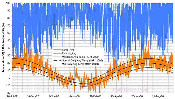
Figure 2: Exterior Temperature and RH During Testing
The interior temperature and relative humidity were controlled for most of the testing period. The relative humidity was kept between 40% and 50% for most of the testing period. As the test walls have sealed drywall air barriers and continuous polyethylene vapor barriers, interior moisture loads do not affect the test wall hygrothermal conditions.
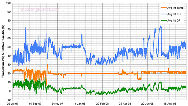
Figure 3: Interior Temperature and RH During Testing
One of the performance criteria for analysis and comparison of the two different wall design approaches is the drying potential. The drying potential was evaluated using a wetting apparatus to inject a known volume of water into a known location in the test wall. The wetting apparatus is shown in Figure 4.
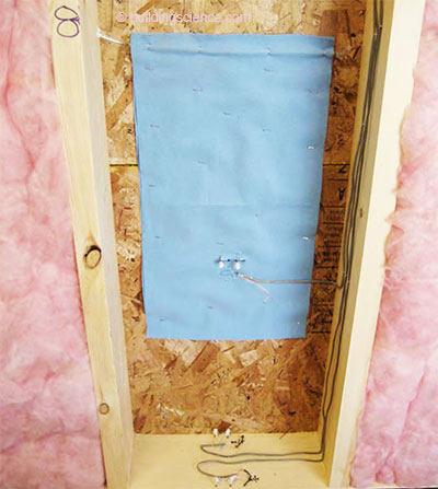
Figure 4: Installed Wtting Apparatus in a Test Wall
The wetting apparatus consists of a water storage and redistribution media (blue material), and an injection tube to inject water without opening the wall, and thereby disturbing the stud space conditions. Only the first intentional wetting event is included in this paper. The wetting event began on the morning of September 16. Each morning and evening 42.5 grams (1.5 ounces) of water was injected for 4 days for a total of 340 grams (12 ounces). This was intended to simulate a small but steady leak into the enclosure from, for example, a small leaky window, or a failed flashing, during a particularly severe storm. . .
Download complete document here.