There is a large existing stock of uninsulated mass masonry buildings: their uninsulated walls result in poor energy performance, which is commonly addressed with the retrofit of interior insulation. Some durability issues associated with interior insulation have been or are being addressed, such as interstitial condensation and freeze-thaw damage issues. However, another durability risk is the hygrothermal behavior of moisture-sensitive wood beams embedded in the load-bearing masonry. Interior insulation reduces the beam end temperatures, reduces available drying potential, and results in higher relative humidity conditions in the beam pocket: all of these factors pose a greater risk to durability.
Introduction
There is a large existing stock of uninsulated mass masonry buildings: their uninsulated walls result in poor energy performance, which is commonly addressed with the retrofit of insulation. Although exterior insulation retrofits provide ideal protection of the existing structure (Hutcheon 1964, Nady et al. 1997), they are incompatible with goal of the preservation of the historic exterior appearance. Therefore, interior insulation of these buildings has become increasingly common.
Some durability issues linked with previous insulation techniques have been or are being addressed, including interstitial condensation and brick freeze-thaw damage However, another durability risk that has received less investigation is the hygrothermal behavior of moisture-sensitive wood beams embedded in the load-bearing masonry. With the retrofit of interior insulation, the embedded beam ends will spend longer periods at colder temperatures than their pre-retrofit condition. Therefore, these wood members will have reduced drying potential due to reduced heat or energy flow (as described by Lstiburek 2008). The wood will also be subjected to higher relative humidity (RH) conditions in the beam pocket, and therefore remain at a higher moisture content (MC): both of these factors increase the risk to the beam’s durability.
Therefore, three-dimensional thermal simulations were performed to examine the effect of interior insulation on embedded wood members. Simulations were run for the cases both of large wood members (“beams”) and smaller dimension lumber members (“joists”). In addition, simulations were run of various methods that would allow increased heat flow to the beam ends, including the use of passive (non-heated) metal “spreader” plates that bypass the insulation; use of less insulation at the beam pockets; and the elimination of insulation at the area surrounding the embedded member. The effect of these methods on overall heat loss through the opaque wall was also examined. The results of these thermal simulations were also used in conjunction with one-dimensional hygrothermal simulations to gain greater insight into the beam end behavior.
Previous Work
Interior insulation of mass masonry wall assemblies in cold climates poses some specific challenges, including interstitial condensation of interior-sourced moisture (at the insulation-masonry interface), and risks of freeze-thaw damage to the exterior masonry. Literature on this practice spans back several decades. Rousseau and Maurenbrecher (1990) provide an overview of the issues faced when adapting existing massive masonry buildings for current use. The overview paper by Gonçalves (2003) gives best practice recommendations for retrofitting insulation to massive masonry structures, based on existing practice in the Montreal region. Like Rousseau and Maurenbrecher, he emphasizes controlling both exterior rain penetration, and air leakage and vapor diffusion from the interior. In addition, he recommends limiting thermal insulation, in order to limit the reduced temperatures at the masonry. The problems and solutions are also outlined by practitioners such as Maurenbrecher et al. (1998), and Straube and Schumacher (2002, 2004).
Masonry freeze-thaw issues (due to reduced outward heat flow and drying) have been examined by Mensinga et al. (2010) (among others). They suggest the use of material property testing (determination of critical degree of saturation, or Scrit) as an input to hygrothermal simulations, using a limit states design approach.
The embedded floor joist decay issue has been studied by several practitioners, including field monitoring and computer simulations.
Dumont et al. (2005) monitored moisture content of wood structural members embedded in masonry in two low-rise residences that were retrofitted with insulation in Wolseley, SK (DOE Zone 7, “dry” climate) and Kincardine, ON (DOE Zone 6A, “moist” climate). The Wolseley house was insulated with mineral wool, with a polyethylene vapor barrier; the Kincardine house was insulated with spray polyurethane foam. The foam insulation encased the wood members where they were seated in the masonry wall. Data showed that the wood members of the Wolseley house remained at safe moisture content levels (10-15%) throughout the monitoring period. However, the Kincardine house showed consistently elevated moisture contents (20%+) at several locations. It was suspected that the moisture source was capillary uptake from the wet foundation, but rainwater absorption through the face of the masonry (due to surface detailing) was not eliminated as a possible source. The limited drying to the interior available through spray polyurethane foam was also likely a contributing factor.
Scheffler (2009) examined the problem of interior retrofits of masonry structures, focusing on moisture problem at wooden beam ends. He used DELPHIN twodimensional hygrothermal simulation software to examine the geometry of a wooden beam embedded in brick masonry under steady state conditions (23° F/-5° C/80% RH exterior; 68° F/20° C/50% RH interior; 90 days). These simulations indicated the moisture risks associated with insufficient control of airflow or moisture vapor flow (diffusion) from interior sources. This was followed by one-dimensional and two-dimensional simulations using transient weather data (Bremen; mild, maritime climate with high rain and humidity), indicating increases in relative humidity and liquid water (condensation) at the beam ends due to the addition of insulation.
Scheffler also described the historic methods to increase embedded beam longevity, such as charring the beam end to increase moisture resistance, and the addition of exterior-to-interior ventilation at the beam pocket. He discussed current methods to ameliorate these moisture issues due to insulation retrofits, including replacement of wood floor/ceiling assemblies with non-moisture sensitive materials (e.g., concrete), and possibly the addition of heat and/or ventilation at the wood beam end.
Morelli et al. (2010) collaborated with Scheffler, continuing examinations of this issue. They proposed the solution of leaving a gap in the insulation of 12” (300mm) above and below the floor, resulting in a 30” (770 mm) gap (12” gap×2 plus floor depth). Two- and three-dimensional heat transfer simulation showed that the heat flow was reduced by 60% going from the uninsulated to insulated cases, while the “gap” case was only a 45% reduction. This work was followed by two-dimensional DELPHIN hygrothermal simulations of the embedded beam (in a Bremen climate). Relative humidity levels in a corner of the beam pocket (and equilibrium wood moisture content) were compared between cases. The existing, uninsulated wall showed a drying trend; the fully insulated wall showed seasonal increases in RH; and the gapped insulation wall showed performance between the two previous cases (but with increasing moisture levels). However, these results assumed a relatively high wind-driven rain loading factor: switching to a lower loading factor, the gapped insulation assembly showed a general drying trend.
Thermal Simulations
The first portion of the work was to run three-dimensional finite-element thermal simulations using HEAT3 v. 5.1 (Blomberg 1996), to examine the effect of interior insulation on embedded wood members. Simulations were run for the cases both of large wood members (“beams”) and smaller dimension lumber members (“joists”).
The simulated “beam” case was a 12” x 8” (0.3 m x 0.2 m) beam embedded in an 18” (0.45 m) thick masonry to a depth of 8” (0.2 m). A 78” x 78” (2 m x 2 m) square section of wall was simulated; the associated wood flooring was also included. A 1” thick (25 mm) cast iron or steel bearing plate is commonly used to spread the beam loads on the masonry; it has the added benefit of acting as a capillary break. This element was explicitly modeled (shown in pink). Beams are often “fire cut,” with the end cut angled inwards to allow for beam collapse without disrupting the surrounding masonry; this was not modeled. Note that these dimensions remain identical throughout these simulations; differences in images are due to aspect ratio shifts in the graphic.
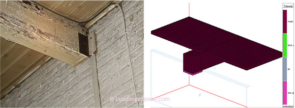
Figure 1: Typical embedded beam (left), and HEAT3 representation of beam, floor, & plate (right)
Interior temperature was fixed at 68° F (20° C), and exterior temperature at 7° F (-14° C), which is the Boston 99.6% design temperature. The interior heat transfer coefficient was modified at two- and three-sided inside corners (wall-beam-floor intersection conditions, 6”/150 mm width), to account for the effect of reduced heat flow at these conditions.
The baseline uninsulated case is shown in Figure 2 (Case 1); beam end surfaces range from 28 to 44° F (-2 to 6° C). The heat conduction through the bearing plate is clear from the asymmetric temperature distribution. Note that the coldest portions of the beam would actually not be present assuming a fire cut end. These simulations assume steady-state conditions, so no benefit from the thermal mass of the masonry is reflected here.
In addition, some early cases examined the effect of the air space that typically surrounds the beam in the pocket: a ~¼” (6 mm) gap was used. The beam end temperatures were close to identical in the air gap and non-air gap cases; this might be explained by the small size of the gap, and the relative thermal conductivities of air at 0.0043 Btu·in / (hr·ft2·°F) or 0.03 W/m·K (R-4.8/inch) vs. wood at 0.0144 Btu·in / (hr·ft2·°F) or 0.1 W/m·K (R-1.4/inch). Results were identical after setting air thermal conductivity to twice the previous value (R-2.2/inch). Note, however, that an air space has a significant effect in terms of capillary liquid water transport between the masonry and the wood.
This was followed by cases which added 2”/50 mm of spray foam insulation (R-12/RSI 2.1) to the interior surface of the masonry (Figure 2, Case 2). The surface temperatures of the beam end dropped to the 12-22°F (-5 to -11° C) range. These cold temperatures penetrate into the “core” of the beam; a temperature distribution at a horizontal section is shown in Figure 4.
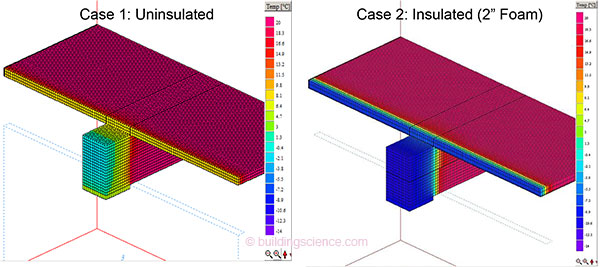
Figure 2: Embedded beam uninsulated case (left) and insulated case (right)
This was followed by simulations of methods to increase heat flow at the beam end, which increase the post-retrofit beam end temperature. One approach was to install thinner (1”/25 mm) thick foam in an area 16”/0.4 m around the beam; a minimum thickness was included to provide an air seal at the beam penetration (Case 3). The resulting temperature distribution (Figure 3, left) appears very similar to the original insulated case (same beam end temperatures; slightly warmer sides).
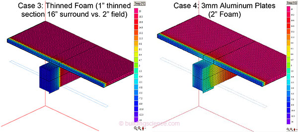
Figure 3: Thinned foam case (left) and 3 mm thick aluminum plates case (right)
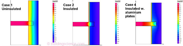
Figure 4: Beam cases horizontal section at mid height in beam: uninsulated (left), insulated (middle), and aluminum spreader plates (right)
Another option was to add metal plates to the sides of the beam, to bypass the insulation (Case 4). After several iterations, a pair of 3 mm aluminum plates was selected; they extended to the full depth of the beam pocket, and had an exposed length of roughly 2 times the pocket depth on the interior. These were simulated as having full contact with the beam. The results in Figure 3 (right) show that the vertical faces of the beam are close to the original, uninsulated temperatures (Case 1), but the middle of the beam is as cold as Case 2. This shows the limitation of the geometry of the problem: wood has a relatively high insulating value, thus making the nominal goal of “transmitting” heat laterally into the pocket more difficult. . .
Download complete document here.