Electrically commutated motors (ECM) in air-handler fans promise improved efficiency. But does improved technology necessarily mean efficient HVAC systems? This article was first published in Home Energy, May/June 2010. Reprinted with permission.
The two technologies used in furnace and air handler blower motors are permanent split-capacitor (PSC) or induction motors and, more recently, electronically commutated motors (ECMs), which are also known as brushless DC motors. ECMs can offer gains in efficiency, especially when their variable-speed capacity is utilized (for example, with a continuous low-speed fan for circulation and destratification, low-speed heating mode). These ECMs are widely used in higher-end furnaces and air handlers (typically referred to as variable-speed units); they are used especially in efficiency-focused work and high-end residences.
A full background on the use of ECMs in air handlers is not the focus of this article. The subject has been discussed at length in previous issues of Home Energy (see "The Electric Side of Gas Furnaces," HE Nov/Dec '03, p. 24; and "Motors Matter," HE July/Aug '00, p. 31). This article focuses instead on air handler energy use and fan efficiency. It is based on a study conducted in 2009 by the Building Science Corporation (BSC), where I work, for the Building America Program. It includes a survey of previous research, and it discusses the results of field measurements. Note that this study is by no means a large-scale survey. However, this research for this study was a matter of particular interest to BSC, given the push toward higher- and higher-performance houses in the Building America program. As enclosure improvements reduce heating and cooling loads, the smaller electrical loads—including the parasitic loads of the air handler motor—become more significant, and thus worth measuring.
Background . . . and a Plea for Sanity
I began my research by conducting a survey of previous work on this topic. Having done so, I have to send out a plea for sanity: There are a lot of air handler efficiency metrics out there, all of them measuring the same thing. They include CFM/watt, watt/CFM, watts/1,000 CFM, and kW/CFM. I personally prefer metrics of efficiency that are of the form output divided by input. This type of metric increases with improved efficiency, much like such common examples as miles per gallon (mpg), annual fuel utilization efficiency (AFUE), seasonal energy efficiency ratio (SEER), and heating seasonal performance factor (HSPF)—which are efficiency metrics for cars and trucks, furnaces and boilers, air conditioners, and heat pumps, respectively. However, it appears that the majority of the industry leans toward watt/CFM (W/CFM). As a compromise, this article will use the first two metrics.
My survey of previous work on this topic was taken from many sources, including standards and test procedures, simulation assumptions, laboratory measurements, and field surveys (see Table 1). Some of the numbers and what they mean are described in detail below.
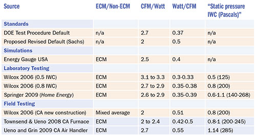
Correction: 0.55 W/CFM value in last row should be 0.37 W/CFM
Standards
The DOE procedure for testing air conditioner SEER assumes a default air handler fan efficiency, given that exterior condensers are combined with a variety of interior units. This default value is an unrealistically high efficiency, compared to common field measurements.
Sachs and others (2006) proposed an alternate default, which is consistent with field surveys of real HVAC equipment.
Simulations
Detailed hourly simulations need to assume an air handler fan efficiency. The value used by the simulation Energy Gauge USA for ECMs is shown. For reference, PSC motors are given the value of 2.0 CFM/W or 0.5 W/CFM.
Laboratory Testing
Wilcox and others (2006) in California provided laboratory measurements of air handler efficiencies at two external static pressures: 0.5 inches of water column (IWC) and 0.8 IWC, or 125 and 200 Pa. Results are shown in Table 1 for the ECM air handlers; efficiency drops with increasing static pressure. Springer’s study of high-minimum-efficiency reporting values (high-MERV) filters included ECM air handler efficiency figures over a range of pressures. (See “Is There a Downside to High-MERV Filters?” HE Nov/Dec ’09, p. 32.)
Field Testing
The 2.0 CFM/W or 0.5 W/CFM median figure comes from a 2005 California field survey of 60 furnace systems (Wilcox et al.; motor type not specified), and is a reasonable representation of installed efficiencies of air handler fans. One result of this research will be California standards on air handler minimum-efficiency levels. Building Science Corporation (BSC) tested four field-installed ECM air handlers in California in 2007. As in many of the previous studies, efficiency was hampered by high static pressures. BSC also tested an additional ECM air handler in California in 2009, with similar results.
So what do these numbers mean? Overall, measured air handler efficiencies for ECM models varied from 2.0 to 3.3 CFM/W (0.33 to 0.50 W/CFM)—ranging from barely better than the median air handler efficiency to substantially better. This range straddles the assumed fan efficiency value used in simulation programs (2.5 CFM/W or 0.4 W/CFM).
Furthermore, high static pressures are sadly the norm in installed equipment. Systems were typically far from the 0.50 IWC/125 Pa level recommended by manufacturers. This is a particular problem with ECMs; their controls are designed to increase fan speed (and thus energy use) to provide a specific programmed flow, using feedback to determine if the target is being met. Therefore, highly restrictive duct systems directly reduce air handler efficiency, due to equipment strain to reach the air flow target at high speeds.
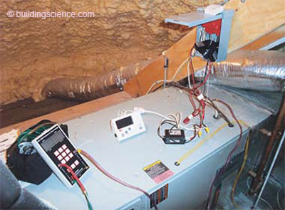
Measurement procedure, showing digital manometer (Energy Conservatory DG-700) and power meter (The Energy Detective). TrueFlow airflow measurement plate is inside filter slot.
Doing the Measurements
We continued with measurements of an ECM air handler installed in our facility. Variable-speed air handlers are typically field configurable for a range of air flows; this model could be set up to provide air flow for 1.5 to 3 tons of cooling, with additional settings within that range (350, 400, or 450 CFM/ton). A hydronic hot water coil fed by a condensing gas boiler provides heating; cooling is provided by a 2.5-ton outdoor condenser; a 5-inch MERV 11 pleated media filter is installed. The cooling coil is an integrated portion of the air handler cabinet, as opposed to an add-on coil.
To measure air flow and electrical power draw, we used common equipment available to most home performance contractors. Air flow was measured with an Energy Conservatory TrueFlow plate flowmeter located in the filter slot. Our previous fieldwork compared TrueFlow results with an Energy Conservatory Duct Blaster fan as a powered calibrated orifice at the air handler; results were relatively consistent.
These air flow measurements are complicated by the fact that ECM air handlers “seek” their target air flow, so they will react to a change in the system flow resistance by increasing or decreasing fan speed accordingly. As a result, the actual flow typically must be calculated with a correction determined by the supply plenum pressures in the two conditions. However, in this case, the TrueFlow plate was close enough in air flow resistance to the installed filter that this correction was an average of 2% of total air flow. Of course, the power measurement must be taken at the correct corresponding state.
Electrical power use was measured with a meter from The Energy Detective (TED), temporarily installed at the electrical disconnect box for the air handler. This unit was used instead of a plug-in meter such as a Kill-A-Watt because these were 220V hard-wired units. The TED has a manufacturer-stated accuracy of ±2%; however, it has a resolution of only 10 watts.
Show Me the Data
My first few measurements of power use were down around 30–80 watts, and my immediate reaction was “Oops … I must have something hooked up backward!” To me, air handler draws are supposed to be up in the 500W–1,000W range. I double-checked with an amp clamp and found similar results, much to my puzzlement. It then dawned on me that I had the air handler on a relatively low setting (350–550 CFM). I cross-checked with the manufacturer’s specifications, and this lined up with their numbers for this speed range. For reference, the fan efficiencies at this low end are roughly 5 to 8 CFM/W (0.15 to 0.20 W/CFM).
I then ramped the air handler through a range of air flows while measuring power draw, but leaving the duct system in its as-found condition. The resulting air flow versus watt draw relationship is shown in Figure 1.
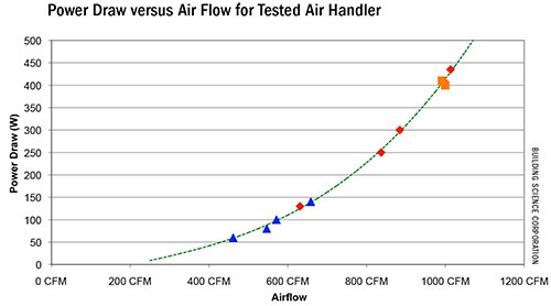
Figure 1: The figure demonstrates that the horsepower varies with the cube of the RPM
(and therefore the cube of the CFM).
Those of you who pay attention to geeky things might notice that this is a demonstration of the fan laws (well … almost—see below). It demonstrates, specifically, that the horsepower varies with the cube of the RPM (and therefore the cube of the CFM). Therefore, for instance, doubling the air flow (CFM) results in 8 times the power draw. . .
Download complete document here.