Thermal Metric Test Wall Construction and Installation
The Thermal Metric (TM) research project uses a novel hot box apparatus to investigate multiple factors that contribute to thermal performance, including thermal bridging, temperature effects, and air flow interactions. The following explains how test walls are constructed and instrumented. For more details about the overall design of the hot box, see Thermal Metric Hot Box Apparatus.
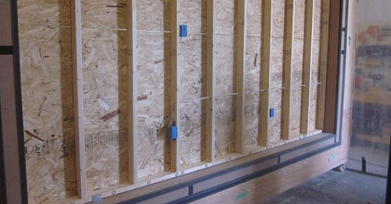
Figure 1: Thermal Metric test wall during construction
Construction and Installation Process
The following process depicts a normal construction process for a 2x4 framed test wall.
- Framing materials are chosen from a selection of moisture content equilibrated framing lumber of similar average densities.
- The 95 in x 143 1/8 in (2410 mm x 3635 mm) stud wall is framed on a level surface without affixing the sheathing.
- Two heavy beads of removable caulking are placed on the cartridge below the location of the bottom plate for air sealing purposes.
- The wall is lifted into place, squared and shimmed to match the cartridge frame, and held in place with clamps at a depth that allows the OSB to be installed flush with the front of the cartridge.
- 7/16 in (11 mm) OSB sheets are installed horizontally and offset by four feet using shims at the top and bottom plate to create gaps at each fastener. Sheathing is then affixed according to the recommendations made in the APA Engineered Wood Construction Guide.
- Two electrical outlets and a switch are installed as per standard practice.
- Backer rod and sealant are installed on the left, right, and top of the wall to complete the wall-to-cartridge air sealing.
- Insulation is installed as per manufacturer’s recommendations.
- Interior gypsum wall board is installed on the interior surface using shims at the top and bottom plate to create gaps at each fastener.
- Building wrap is installed over the exterior OSB as per the manufacturer’s recommendations.
- The vertical edges of the building wrap are taped to the cartridge.
- 4 in (100 mm) vinyl siding is installed as per the Vinyl Siding Installation Manual.
- The interior and exterior surface thermistor arrays are installed and tested.
- The wall system is inspected and photographed.
- The cartridge containing the wall is installed into the test box.
- An air leakage test is performed before testing commences.
Temperature Measurement Locations
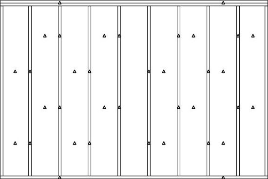
Paired temperature measurements are made on opposite sides of the test specimen using calibrated thermistors. The sensor locations on the meter box side are replicated identically on the climate box side, such that each location has a sensor on either side of the wall sample. The thermistors are attached directly to the surface of the specimen using a three layer taping assembly. Two layers of aluminum tape sandwich the sensor and are used to average the local temperatures. A mat-black top tape layer is used to cover the reflective foil tape to create a radiatively homogeneous surface. Figure 2 shows an instrumentation grid typical of the test walls. Stud, stud bay, and top and bottom plate temperatures, and hence temperature differentials, are measured.
Figure 2: Typical temperature measurement locations for test walls
As-Built and Sealed Walls
Each of the tested reference walls was built with intentional air leakage paths across the assembly. Imposed gaps were created using 1/32 in (0.8 mm) spacers affixed to the top and bottom plates. The spacers were located at each fastener on both sides of the assembly between top and bottom plate framing and the exterior sheathing and the interior drywall.
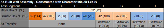
A 1/8 in (3.2 mm) horizontal mid-height gap between the sheets of exterior OSB sheathing was installed as per APA installation requirements. The combination of the imposed gaps at the top and bottom plates and the horizontal gap in the sheathing provided a repeatable air flow leakage path through the assembly, representative of standard construction practices. Each assembly was tested with these gaps and was labelled an As-Built assembly. Table 1 contains the test points for each As-Built assembly.
Table 1: As-built testing
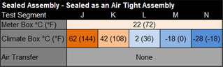
Once the As-Built testing was completed, the cartridge was removed from the testing apparatus and sealed on both sides using polyethylene sheet and a combination of tapes. The cartridge was then re-installed, an air leakage test was conducted, and then the samples were tested to the setpoints shown in Table 2
Table 2: Sealed testing
Materials Used
A variety of wall assemblies have been tested, including the most common insulation materials in various configurations in 2x4 framing. Initial test walls (Phase II of the TM Project) created reference values for seven assemblies that represent common North American construction methods. Five wall assemblies were constructed to achieve a nominal insulation R-value of 13 (RSI 2.28), using 2x4 framing at 16 in (406 mm) on center. The following stud-space insulation materials have been tested:
- Inset-stapled kraft-faced fiberglass batt
- Face-stapled kraft-faced fiberglass batt
- Damp-sprayed cellulose fiber insulation
- Open-cell sprayed polyurethane foam
- Closed-cell sprayed polyurethane foam
Two additional assemblies were constructed and tested to compare the thermal performance of higher R-value assemblies. The higher R-value assemblies were:
- 2x4 @ 16" (406 mm) o.c. with nominal R13 (RSI 2.28) friction-fit fiberglass batt + nominal R5 (RSI 0.88) 1" (25.4 mm) XPS exterior insulating sheathing
- 2x6 @ 16" (406 mm) o.c. with nominal R21 (RSI 3.70) friction-fit fiberglass batt
Future testing will investigate other factors that affect the effective thermal resistance of the wall assemblies. This testing is to include variables such as the thickness, type, and placement of various insulation materials to create high R-value assemblies.