A single-story, single-family, 1350 sq. ft. house located in Las Vegas, NV was outfitted with two separate ventilation systems. The systems were independent of each other, and were operated at different times to evaluate the relative difference in air change rate and distribution of ventilation air induced by their operation. Energy efficient homes inherently have low air leakage rates and, therefore, require mechanical ventilation for acceptable indoor air quality.
Introduction
Energy efficient homes inherently have low air leakage rates and therefore require mechanical ventilation for acceptable indoor air quality.
Supply ventilation systems draw outside air from a known location and deliver it to the interior living space. This known location should be selected to maximize the ventilation air quality. The air can be treated before distribution to the living space (one or more of: heated, cooled, dehumidified, filtered, cleaned). If supply ventilation air is not pre-treated, it should be mixed with re-circulated indoor air to mitigate discomfort effects of the outside air. Supply ventilation will tend to pressurize an interior space relative to the outdoors, causing inside air to be forced out through leak sites (cracks, holes, etc.) located randomly in the building enclosure. This strategy is advantageous in warm-humid climates to minimize moisture entry into the building structure from outdoors.
Supply ventilation systems can be powered and ducted in many different ways. How the system is powered, i.e. how fresh air is forced into the house, will effect the first cost and operating cost. How the system is ducted will affect the first cost and the capacity of the system to distribute ventilation air uniformly to all occupied spaces in the home.
The focus of this study was to evaluate the effectiveness of two different supply ventilation systems in providing adequate air change rates and uniform distribution of fresh air. Both of the ventilation systems tested have been used by production builders as part of the USDOE Building America Program, Building Science Consortium. The
central-fan-integrated supply ventilation system is being used extensively.
Test Setup
Two ventilation systems were installed in the same 1350 ft2 house, in Las Vegas, NV, to individually evaluate their effectiveness in providing adequate air change rates and uniform distribution of fresh air throughout the house.
One system was central-fan-integrated supply ventilation, wherein, outside air was ducted from a high wall location on the building exterior to the return air side of the central heating and cooling system blower (Rudd 1998). This system utilized the existing central heating and cooling system ducts and blower to provide ventilation air and conditioned air at the same time. A FanRecyclerTM control (The News1998, Builder 1998, EDU 1997) is used to periodically cycle the central blower to distribute ventilation air and provide mixing during stagnant periods when there is no thermostat demand to circulate air for purposes of heating or cooling. A schematic of the central-fan-integrated supply ventilation system installed in the test house is shown in Figure 1. In this house, the attic was not vented, and the roof insulation was applied directly under the roof sheathing - called a "sealed-cathedralized" attic (Rudd, Lstiburek 1998). Hence, the attic mounted air handler and ducts were inside conditioned space, eliminating air distribution system losses. The outside air duct was a four inch diameter expanded aluminum duct connected to a four inch wall cap at the exterior wall and connected to a register box, modified to hold a standard 12"x12" filter, at the return plenum of the central heating and cooling air handler unit. The outside air duct was undersized for this house, allowing in only 47 ft3/min through the four inch duct. The target outside air flow for this house was 80 ft3/min according to Eq. 1 and the following given parameters:
- 40 ft3/min continuous ventilation required for the occupants of the three bedroom house
- 33% central fan duty cycle
- 0.10 air changes per hour in-between central fan cycles
- house volume of 12,150 ft3
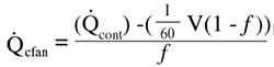 Eq. 1
Eq. 1where:
Qcfan = intermittent outside air flow rate through the central fan (ft3/min)
Qcont = continuous outside air flow rate required (ft3/min)
I = estimate of natural air change when central fan is not operating (1/h or ach)
V = volume of conditioned space (ft3)
f = fan duty cycle fraction
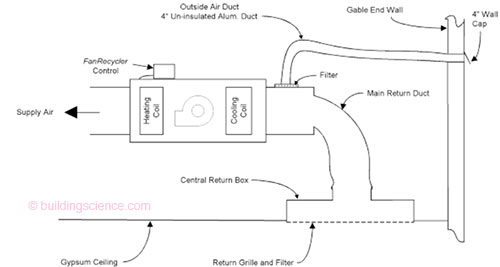
Figure 1: Schematic of central-fan-integrated supply ventilation as installed in the house tested
The actual outside air flow was measured two ways, using a calibrated fan and a velocity probe. The pressure in the outside air duct was -52 Pa with respect to outdoors. To achieve the target 80 ft3/min of outside air with this configuration, a five inch diameter insulated flex duct with a six inch wall cap and a balancing damper should be used. Outside air duct pressure should be adjusted with the balancing damper to obtain -30 Pa upstream of the balancing damper. A number of configurations have been used to conduct outside air to the air handler return for effective air flow and filter access. Recommendations are given in a further section of this paper.
The second system was a separate supply ventilation system, not connected to the central air distribution ducts, wherein, a separate fan drew 54 ft3/min of outside air and 112 ft3/min of inside air from the master bedroom and delivered the 166 ft3/min of mixed air to the main living area of the house. Figure 2 shows a schematic of this system. The flows used followed a 1:2 ratio of outside air to re-circulated air, based on the existing outside air flow of the central-fan-integrated system. Air flows were measured and balanced using a calibrated fan and velocity probe. Re-circulated inside air was drawn from the master bedroom instead of the main living area to test the hypothesis that fresher air from the main living area would tend to move back to the master bedroom to replace the re-circulated air. Depending on the house layout, this would likely raise the system first cost, but far less than a fully-ducted separate system.
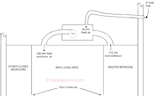
Figure 2: Schematic of separate supply ventilation system installed in the house tested
Air change rate and ventilation air distribution effectiveness was measured using a computer controlled multi-zone gas analyzer. Sulfur hexafluoride (SF6) was the tracer gas. The gas analyzer was setup to measure SF6 concentration at approximately two minute intervals in six locations: southeast bedroom, southwest bedroom, main living area hall, living room, master bedroom, and master bathroom. Decay of the tracer gas gives the air change rate according to Eq.
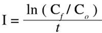 Eq. 2
Eq. 2where:
I = air change rate (1/h or ach)
Cf = final concentration
Co = initial concentration
t = time (h)
During the testing, all interior doors were closed to represent overnight sleeping conditions. It is during this time that effective distribution of ventilation air is most needed.
Results
Testing commenced on 8 August 1998 at 2 pm and ended on 10 August 1998 at 9 am. To begin testing, the central heating and cooling system fan was turned on and SF6 tracer gas was released into the return air grille. As the fan continued to operate, the tracer gas was mixed throughout the house until, after about 45 minutes, a uniform concentration of about 4 parts per million (ppm) was reached.
At this point, the first test period for the central-fan-integrated supply ventilation system began. The thermostat fan switch was left in the ON position, and the outside air duct was open. Since it was also hot outside, the thermostat system switch was left in the COOL position causing the compressor to cycle in response to thermostat demand.
Table 1 shows the air change results for tests of the central-fan-integrated supply ventilation system and the separate supply ventilation system. For the first central-fan-integrated ventilation test (Test ID 1), with the central fan operating constantly, a very uniform air change rate of between 0.33 and 0.34 was achieved in all six of the monitored spaces.
Table 1: Multi-zone air change rate measurements for central-fan-integrated supply ventilation and separate supply ventilation
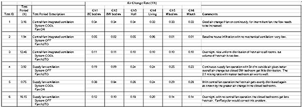
To obtain a baseline air change rate for the house (Test ID 2) without heating or cooling or ventilation operation, the thermostat system mode switch was turned to OFF, the thermostat fan switch was turned to AUTO, and the FanRecycler was turned OFF. As shown in Table 1, the baseline infiltration was very low, between 0.01 and 0.06, and not very uniform across the six zones. However, within each zone, the air change rate was consistent. The master bedroom and master bath, which were one zone, had the lowest air change rate (0.01), similar to the southwest bedroom (0.02). The main living area zone, which was represented by the hall and living room sampling locations, and had the highest air change rate (0.05 to 0.06), along with the southeast bedroom (0.05).
The second central-fan-integrated ventilation test (Test ID 3) represented normal operating conditions. The thermostat system switch was set to COOL, the thermostat fan switch was set to AUTO, and the FanRecycler was turned ON. The FanRecycler was set to operate the fan for 10 minutes if it hadn't operated for 20 minutes, giving a 33% duty cycle. During this 12.46 hour test period (overnight), the air change rate averaged between 0.10 and 0.11 for all of the monitored locations. This demonstrates that very uniform distribution of ventilation air can be achieved by central-fan-integrated ventilation with normal cycling of the central fan. However, as stated in the previous section, the volume of ventilation air flow was too low due to an undersized outside air duct.
Before the beginning of the separate supply ventilation tests, tracer gas was again injected into the house with the central fan operating continuously. However, this time it was injected into the outside air duct wall cap on the exterior of the building, not into the central return air grille. Referring to Figure 3, plotting of the tracer gas growth in all six monitored locations graphically shows how uniformly ventilation air is distributed with the central-fan-integrated ventilation system.

Figure 3: Tracer gas injection into outside air inlet of central-fan-integrated supply ventilation system shows how uniformly ventilation air is distributed throughout the house
Once the tracer gas concentration was uniform throughout the house, the first test of the separate supply ventilation system was begun (Test ID 4). The outside air duct to the return air side of the central fan was blocked off. The thermostat system switch was turned to OFF, the thermostat fan switch was turned to AUTO, and the FanRecycler was turned OFF. This kept the central fan from operating. The separate supply fan was turned on, drawing 54 ft3/min from outdoors and 112 ft3/min from the master bedroom, and suppling the resulting 166 ft3/min of mixed air to the . . .
Download complete document here.