The current owners of this 1993 Colonial style house purchased the home in 2003. After living in the house for several years, they started planning a project to make improvements that would better meet their needs, including a 492 ft2 two story addition on the back of the house, rebuilding the roof over the main part of the house with a steeper slope so that additional living space could be developed in the attic, adding more insulation, and tightening up the house.
Plans for the improvements were well underway when the owners and their builder realized that the project was addressing many of the areas required for the National Grid Deep Energy Retrofit (DER) Pilot program. By joining the DER program, they received technical and financial support that enabled the project to increase the thermal and air tightness goals of the project to DER levels. In addition, insulation of the basement walls was added which contributes not only to energy savings but to improved indoor air quality. The improvements made are projected to reduce source energy use by 29% compared to pre-retrofit conditions.
There are many suburban neighborhoods built within the last 20 years that have similar houses. This project demonstrates the potential for significant energy savings for these newer homes.

Project Team: Basnett Design/Build/Remodel, Contractor; Building Science Corporation, Consultants and DER Technical Support; National Grid, Massachusetts, DER Pilot Program Administrator/Sponsor
Location: Westford, Massachusetts
Description: Major renovation including partial DER of 3,955 ft2 four bedroom, two full and one half bathrooms, three stories plus a partially finished full basement
Completion Date: December 2011
Estimated Annual Energy Savings: Projected 29% source energy use reduction compared to pre-retrofit conditions
Design
When this project joined the National Grid DER Pilot program, plans had already been developed for improving the exterior wall insulation and for creating an unvented conditioned attic. BSC worked with the builder to improve the details for exterior insulation, air tightness, and moisture control.
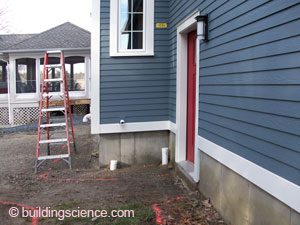
For the exterior walls, rigid insulation was applied over the plywood wall sheathing with either fiberglass batt cavity insulation (in existing walls) or open-cell spray polyurethane foam insulation (ocSPF) (in new walls) to reach DER targets. The exterior insulation was applied in two layers, with joints staggered to minimize air channels and taped on the outer layer to form the drainage plane. New fiber cement siding was fastened to vertical furring strips attached to the structure through the insulating sheathing. The gap that this created between the outer layer of insulating sheathing and the back of the siding provides ventilation and drainage space.
For the roof, closed-cell spray polyurethane foam insulation (ccSPF) was applied directly beneath the roof sheathing and filled the rafter cavities. Where a cathedral ceiling was to be created, an additional layer of 1” insulating sheathing was applied over the bottom of the rafters, to be covered with drywall. For attic spaces, the depth of the spray foam insulation was increased to encapsulate the rafters. Both methods reduce the thermal bridging that can occur when insulation is applied on the inside of a roof deck.
Those portions of the basement that were finished space had an existing perimeter 2x4 stud wall placed ½” inside of the foundation wall. On these walls, the area between and behind the studs was filled with 4” of ccSPF. Where there was to be future finished space, a similar approach was taken. For the unfinished sections of the basement, 3” of rigid insulation was applied directly to the concrete foundation wall.
The basement floor was left uninsulated except where the new basement was built. In the new section, insulation was installed below and along the edges of the new slab.
The existing gas furnace and gas water heater already met the DER requirements. Installations of an energy recovery ventilator (ERV) and a more efficient air conditioning system were included in the project.

Image from BSC generated by NREL’s BEOpt 1.2 for retrofits
Enclosure Design
Roof Assembly: R-62 (nominal) unvented roof assembly: asphalt shingles over underlayment and plywood; closed-cell spray foam (ccSPF) insulation in 2x10 rafter cavities; the bottom of the rafters are covered with 1” rigid insulation and drywall in finished cathedral space and with 1” of ccSPF in attic space.

Closed-cell spray foam in unvented roof
Wall Assembly: R-39 (nominal): Fiber cement cladding installed over 1x4 vertical furring strips; two 11/2” layers of polyisocyanurate insulating sheathing (outer layer foil-faced, inner layer fiber reinforced facing) with seams staggered and taped on the outer layer; plywood sheathing with seams taped; 2x6 walls filled with fiberglass batts (existing) or open-cell spray foam (ocSPF) insulation (new).

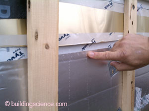
Polyisocyanurate insulating sheathing
Window Specifications: Marvin Integrity double hung, new construction flanged windows, U-Value 0.29, SHGC 0.28, installed in the plane of the insulating sheathing.

Flanged window on insulating sheathing
Infiltration: Air barrier system is as follows: concrete walls in basement; spray foam in cavity of new above grade framed walls, taped sheathing and interior sealing on existing above grade framed walls; spray foam under roof sheathing; transitions made using sealant, spray foam, and caulking.

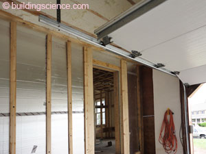
Air barrier system at eave
Foundation Assembly: Unfinished basement walls insulated with 3” of taped polyisocyanurate insulation below grade and additional 3” polysiocyanurate above grade; finished or to-be-finished basement walls insulated with 4” of ccSPF below grade and additional 2” polyiso above grade. Existing basement slab was not insulated. New basement slab has 2” XPS insulation below.

Unfinished basement walls
Construction
The builder used two different types of polyisocyanurate exterior insulating sheathing for the insulation on the exterior walls. The inner layer has a fiber reinforced facing and the outer layer has a foil facing. Tape does not adhere well to fiber reinforced facing. However, taping of the seams of the inner layer of insulation is not necessary since the seams of the outer layer of insulation were taped to create the drainage plane. The builder also taped the seams of the plywood wall sheathing which reduces potential air channels through the wall assembly.
The closed combustion gas fireplace was changed from chimney-vented to sidewall-vented. All but the lowest section of the original non-masonry chimney was removed and the remainder received the same wall and roof assembly treatment as the rest of the house.
The project opted to use Marvin Integrity windows rather than windows that would meet the DER target. This was because comparably priced triple-glazed windows are currently available only with vinyl or fiberglass frames – forcing the owner to choose between the desired aesthetics (windows with wood interiors) and performance (R-3.4 vs. R-5).
Mechanical Design
Heating and Cooling: Existing closed combustion gas furnace was reconfigured from 1 to 3 zones; new two stage 16 SEER air conditioner unit (American Standard Allegiance 16) with new indoor air coil (American Standard All-Aluminum Efficiency Comfort Coil) attached to existing air handler.

Two stage 16 SEER air conditioner
Ventilation: Renew Aire EV 300 ERV was installed in the basement with a dedicated duct system; the outdoor supply air is delivered to the kitchen and exhaust air is taken from the finished section of the basement. The furnace air handler fan is set to cycle at regular intervals to distribute the supply air from the kitchen throughout the house. Spot ventilation is provided for baths and gas cooktop.

Renew Aire EV 300 ERV
Space Conditioning Distribution: Heating and cooling air distribution is through ductwork, all of which is in conditioned space except for ducts serving the master bedroom which are within the insulation of the garage ceiling.
DHW: Existing closed combustion A.O. Smith gas water heater.

Domestic hot water heater
Lighting: CFL lighting.

Appliances: ENERGY STAR® appliances.

Energy Star® washer and dryer
Testing and On-Site Technical Support
BSC worked with the builder to resolve technical issues through on-site visits and remote support. Over the course of two different site visits, the window flashing and insulation details were reviewed at different stages. Reviewing along the way allowed for corrections or improvements to be made as needed without impeding the project’s progress.
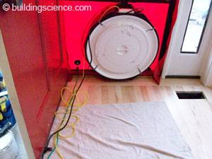
BSC performed pre- and post-retrofit air leakage testing to determine the improvement in the air leakage of the whole house.
The pre-retrofit measurement of 2591 CFM 50 was made with the overhead garage door open and included the basement but not the attic. The post-retrofit air leakage testing measurement of 930 CFM 50 was made with the garage door open and included the basement as well as the overall increased surface area and volume due to the addition and the restructured roof. The post-retrofit measurement is roughly equivalent to 1.7 ACH 50 when using the air barrier boundary to establish the volume.
Moving Forward
As a participant in the National Grid DER Pilot project, the homeowner will provide monthly utility bills for the first two years following the completion of the retrofit. These will be analyzed to gauge the performance of the retrofit strategies employed.
Through participation in this project, the builder increased his toolset for high performance residential construction, particularly for enclosure performance and durability. This will prove useful for both new and retrofit projects in the future.
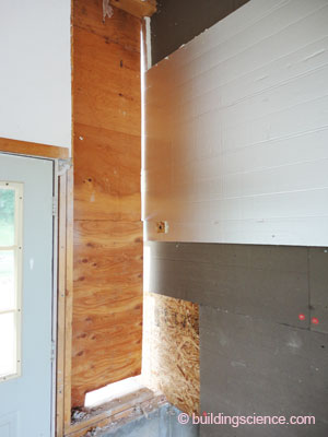
Design Challenge: Isolating an Attached Garage This house has an attached 2-car garage with the master bedroom located directly above. For a project with super-insulation and significantly improved air tightness goals, this condition requires special care. To ensure air separation between the garage and the interior of the house, the air barrier layer of the house at the separation wall and at the garage ceiling requires careful detailing and air tight transitions. For the best thermal performance, there should be no thermal bridges between the garage enclosure and the house enclosure. For this project, the builder was able to completely isolate the front and rear garage walls from the exterior wall of the house. With the siding for the garage removed, the garage wall sheathing and wall framing was cut back creating an opening between the garage walls and the house exterior wall. The air barrier and exterior insulation layers of the exterior wall of the house were then extended continuously through the garage wall connections.
|