In 1920, when this house was built on the bank of a coastal cove, it served as a summer cottage complete with a boat dock. Over the years, the house has been remodeled, added to, and converted to a year-round residence. Now, as part of the latest renovation, it has undergone a deep energy retrofit which is projected to achieve a 43% source energy savings for the occupants. The National Grid Deep Energy Retrofit (DER) Pilot Program provided technical and financial assistance for the energy saving improvements of the renovation.
While the exterior of the house still looks much like it has looked for years, the DER portion of the project has significantly improved the performance and durability of the enclosure on all sides of the house. The above grade portion of the house was wrapped in insulation on the outside and the below grade portion was wrapped in insulation on the inside. In addition, air tightness and water management was improved, mechanicals were replaced with energy efficient systems and a solar hot water system was installed.
The result is an energy efficient, air tight house that is comfortable year round and that should be able to withstand many more years of nor’easters along the Massachusetts coast.

Photo courtesy of Tobias Richon
Project Team: Geoffrey H. Richon Co., Contractor; DEAP Energy Group, Mechanical Design Consultant; Building Science Corporation, Consultants and DER Technical Support; National Grid, Massachusetts, DER Pilot Program Administrator/Sponsor
Location: Gloucester, Massachusetts
Description: Comprehensive DER retrofit of 2,424 ft2 one bedroom, two bathroom, 2-story house with walkout basement
Completion Date: January 2012
Estimated Annual Energy Savings: Projected 43% source energy use reduction compared to pre-retrofit conditions
Design

Image from BSC generated by NREL’s BEOpt 1.1 for retrofits
When this renovation project started, it was clear that new siding, new windows, and new roofing should be included as well as an interior renovation and a strategy for reducing energy use that would meet both the life style and energy saving goals of the owners. Their builder suggested that they participate in the National Grid DER Pilot project which provided both financial and technical support for the energy efficiency measures of the project.
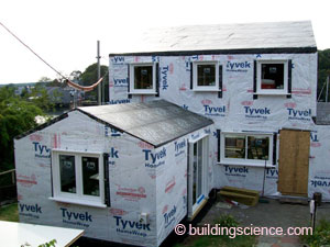
Since the siding and roofing were to be removed, the retrofit strategy for the above grade enclosure was to first wrap the air barrier (housewrap on walls, self-adhered membrane on roof) around the exterior sheathing of the house and then wrap the house in insulating sheathing. This, together with cutting off the overhangs and rafter tails, made it possible to achieve complete continuity of the air barrier and of the thermal layer at the junction between the roof and the walls. New overhangs were built and attached over the insulation.
The strategy was reversed for the basement. Here, the air barrier and insulation layers were applied to the inside of the foundation walls and over the top of the existing slab. The options for providing insulation on the basement slab were limited by the presence of ledge beneath the slab and by a low floor-to-ceiling height in the basement. For this reason, only 1” of insulation could be applied over the slab in the living area of the basement.
The existing windows, which were primarily double hung, were replaced with casement and awning triple-glazed windows for improved air tightness and thermal performance. Replacement of all appliances and an upgrade of mechanicals were also included in the design as well as removal of the existing chimney down to the basement level.
The original mechanical design, developed by DEAP Energy Group using energy modeling tools, called for a mini-split, multi-head air source heat pump system with one outdoor unit and three indoor heads, one of which was a ducted head. The HVAC subcontractor was not comfortable with this approach, so the final design had two outdoor units and five indoor heads, two of which were ducted units. Resistance heating was provided for the bathrooms and as backup. A ducted HRV and a solar hot water system with electric backup completed the mechanical design.
Enclosure Design
Roof Assembly: R-67 (nominal) unvented roof assembly: new asphalt shingles over underlayment and new plywood; three 2” layers of foil-faced polyisocyanurate insulating sheathing with seams offset and taped; continuous layer of fully adhered membrane over existing roof sheathing; 8” of netted cellulose in rafter cavities.

Foil-faced polyisocyanurate insulating roof sheathing (photo courtesy of Tobias Richon)
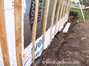
Wall Assembly: R-38 (nominal): Fiber cement cladding installed over 1x4 vertical furring strips; two 2” layers of foil-faced polyisocyanurate insulating sheathing with seams offset and taped; taped housewrap applied over existing board sheathing; existing wall cavities filled with cellulose.

Vertical furring strips over polyisocyanurate
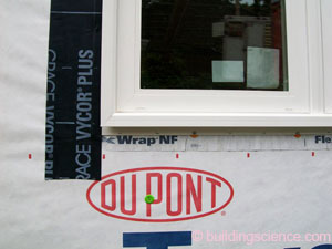
Window Specifications: Mathews Brothers triple-glazed, argon, low-E vinyl, flanged, new construction casement and awning windows, U=0.2, SHGC=0.3; windows installed in alignment with the existing board sheathing.

New consruction triple-glazed windows
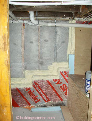
Infiltration: Air barrier system is as follows: existing basement slab with two coats of epoxy paint; taped rigid insulation on inside of foundation walls; spray foam at the rim joist; taped housewrap on above grade walls; fully adhered membrane on existing roof sheathing; transitions between roof and above grade walls made by lapping membrane over the housewrap; other transitions made using sealant.

Spray foam at rim joist (photo courtesy of Tobias Richon)
Foundation Assembly: Conditioned basement with 2.5” of taped XPS insulation and 1” of rigid polyisocyanurate applied to inside of concrete block foundation walls and covered with plywood. Existing basement slab covered with two coats of epoxy paint (for air sealing and vapor control) and then with 2” of XPS rigid insulation except at the workshop area which has no insulation and the living area which has only 1” of XPS.

Taped XPS insulation (photo courtesy of Tobias Richon)
Mechanical Design
Heating and Cooling: Two mini-split multi-head air source heat pump systems with backup electric resistance on each floor and in baths.

Ventilation: Fully-ducted HRV located in attic with exhaust taken from the baths and the kitchen and supply provided to the basement living area as well as to the first and second floors.

Space Conditioning Distribution: Heating and cooling air distribution is via wall-mounted heads for the basement and first floor and horizontal ducted heads (in the attic); return to one of the ducted heads in the attic.
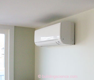
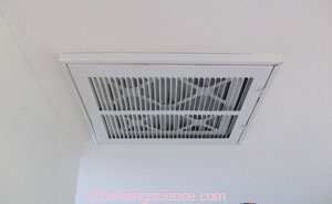
Air distribution (right) and return grille (left)
DHW: Solar hot water system with 28 ft2 of flat plate collector and 92.5 gallon storage tank with an electric immersion heater for backup.

Lighting: ENERGY STAR® CFL lighting.

Appliances: ENERGY STAR® appliances.
Construction
All existing windows, which were primarily double hung, were replaced with casement and awning triple-glazed windows. These were installed in alignment with the existing board sheathing rather than with the outer plane of the exterior insulating sheathing so they appear deeply inset when viewed from the outside. This approach complicates other aspects of the construction because the window drainage occurs behind the insulating sheathing (secondary drainage plane) whereas all other drainage occurs on the outside of the insulating sheathing (primary drainage plane). Care must be taken not to obstruct drainage from either of these drainage planes.
The builder was diligent in developing the air tightness. In addition to replacing the double hung windows with more air tight casement and awning windows, the project established a continuous air barrier layer around the house by wrapping it over the existing sheathing of the above grade portion of the house. The continuity in the transition between the air barrier on the roof and that on the walls was accomplished by cutting off the rafter extensions so that the roof air barrier material (self-adhered membrane) could be overlapped directly onto the wall air barrier component (taped and sealed housewrap).
Photos courtesy of Tobias Richon
Testing and On-Site Technical Support
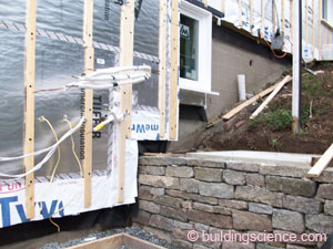
BSC worked with the builder to resolve technical issues through on-site visits and remote support. This included helping with details for thermal, vapor and water control layers for the unique basement conditions—multiple levels dictated by the presence of ledge and a granite retaining wall serving as part of the foundation for a framed wall.
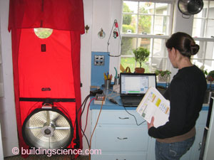
BSC performed pre- and post-retrofit air leakage testing to determine the improvement in the air leakage of the whole house. Since the retrofit included enclosing a porch, the indoor/outdoor boundary of the house was changed during the retrofit. The pre-retrofit measurement representing the existing operational conditions (with basement and attic closed) was 2258 CFM 50, but was 2743 CFM 50 with the basement open (which is closer to post-retrofit conditions). The post-retrofit measurement (including basement and attic) was 236 CFM 50. With the air barrier boundary establishing the total volume, this is approximately equivalent to 0.6 ACH 50.
Moving Forward
As a participant in the National Grid DER Pilot project, the homeowner will provide monthly electric bills for the first two years following the completion of the retrofit. These will be analyzed to gauge the performance of the retrofit strategies employed.
The builder chose to install the windows in alignment with the existing board sheathing rather than with the outer layer of exterior insulation because he felt that would be easier for the window installers. While he would choose to do the same installation again for this house, he now realizes that this is really just an aesthetic decision to be made on a case by case basis for future projects that use exterior insulation.
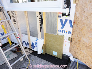
Design Challenge: Preserving the Mudsill During the design process, there was some concern that the changed conditions after the retrofit might trigger moisture problems for the existing mudsill since there was no capillary break underneath it and drying, should it get wet, would be inhibited by the application of impermeable insulation from both the interior and exterior sides. As remediation for this situation, BSC recommended replacing the inner layer of exterior vapor impermeable insulation at the bottom of the wall with vapor permeable semi-rigid mineral wool, thus allowing the wood to dry to the outside. Ultimately the builder decided to use open cell spray foam on the inside which is also vapor permeable, so that the drying potential for the original mudsill has not significantly changed in spite of the changed basement conditions. The builder noted that the sloped site conditions made it difficult to assure that the bottom part of the exterior insulation would stay sufficiently above grade over time. Therefore, noting that mineral wool insulation is water tolerant as well as vapor permeable, the builder carried the above recommendation one step further by replacing the outer layer as well as the inner layer of polyisocyanurate insulation with mineral wool as an enhanced durability measure.
|