Twenty homes were tested and monitored in the hot-humid climate of Houston, Texas, to evaluate the humidity control performance and operating cost of six different integrated dehumidification and ventilation systems that could be applied by production homebuilders. Results showed that energy efficiency measures, combined with controlled mechanical ventilation, change the sensible and latent cooling load fractions such that supplemental dehumidification, in addition to that provided by the central cooling system, is required to maintain indoor relative humidity below 60% throughout the year.
Background
Like year-around temperature control, year-around humidity control in homes is important to improve indoor air quality, building durability, and owner satisfaction1.
In hot-humid climates, constructing thermally efficient building envelopes with controlled mechanical ventilation provides unique challenges for controlling humidity levels2. As the sensible heat load is reduced for a building, primarily through better windows, more insulation, and air distribution ducts inside conditioned space, the latent load increases in proportion to the total load to the point that conventional cooling systems have difficulty keeping humidity levels within comfortable and healthy limits3. Conventional cooling systems are controlled by thermostats that sense temperature and not humidity, hence, during periods of low sensible load and high latent load, high indoor humidity levels can be problematic.
Equipment is available to deal with this challenge in different ways. Ventilating dehumidifiers (both DX and desiccant) are thought to be the best way to control humidity levels separate from the conventional cooling system, but they are often commercial-type systems and are believed to be too expensive to make major inroads with production homebuilders. Additionally, integrating dehumidification with ventilation using “off-the-shelf” dehumidifiers may appear to be primitive and energy inefficient – although costs and benefits have remained speculative due to a lack of data and field research.
The objective of this study was to identify the best performing, most energyefficient and cost-effective techniques to provide controlled mechanical ventilation and humidity control in hot-humid climates with thermally efficient building envelopes. It was known that these strategies vary greatly in first cost. However, the whole-house humidity control performance and operating cost was much less known and therefore was measured. This information was expected to provide the basis for definitive recommendations to production homebuilders on the best commercially available methods to provide their customers with superior residential product at the most cost effective and energy efficient level.
Research Approach
A total of 20 homes were included in the study conducted in cooperation with Pulte Home Corporation in Houston, Texas. Six different integrated dehumidification and ventilation systems were evaluated in homes that were at least 30% better than Model Energy Code 1995. These homes were constructed with unvented-cathedralized (conditioned) attics4,5. Three reference houses had the same energy efficiency measures and controlled mechanical ventilation, but no dehumidification separate from cooling. Three other reference houses met code minimums for energy efficiency and did not have mechanical ventilation or dehumidification separate from cooling, and had conventional vented attics.
A schematic of the central-fan-integrated supply ventilation system used in many of the houses is shown in Figure 16,7. An outside air duct was routed from a fresh air location to the return side of the air handler. A manual damper was installed in the outside air duct to set the flow rate, while a motorized damper was installed to control the air flow volume as a function of time. Outside air was intermittently drawn in by normal thermostat-driven operation of the central cooling and heating system, and, when necessary, by activation of the central air handler blower via a fan cycling control. Control of the motorized damper limited over-ventilation.
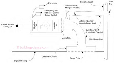
Figure 1: Diagram of central-fan-integrated supply ventilation
A description of the six dehumidification and ventilation systems follows:
System 1: Stand-alone dehumidifier in hall closet with central-fan-integrated supply ventilation (2 homes tested)
The stand-alone dehumidifier system involved installation of an off-the-shelf 50-pint-per-day dehumidifier in an interior closet with a louvered door near the central air return. The dehumidistat built into the dehumidifier energized the dehumidifier whenever the humidity level rose above the user setting. The fan cycling control was set to 33% duty cycle (on for 10 minutes if it had not been on for 20 minutes), to intermittently average air conditions throughout the house and distribute ventilation air.
System 2: Stand-alone dehumidifier in conditioned attic with central-fanintegrated supply ventilation (2 homes tested)
The stand-alone dehumidifier system involved installation of an off-the-shelf 50-pint-per-day dehumidifier in the conditioned attic with a small return air duct located near the dehumidifier outlet. The dehumidistat built into the dehumidifier energized the dehumidifier whenever the humidity level rose above the user setting. The fan cycling control was set to 33% duty cycle (on for 10 minutes if it had not been on for 20 minutes), to intermittently average air conditions throughout the house and distribute ventilation air.
System 3: Ultra-Air Dehumidification and Ventilation System (3 homes tested)
The Ultra-Air system involved installation of a ducted high-efficiency ventilating dehumidifier located in the conditioned attic. The Ultra-Air blower operated continuously on low speed, drawing in about 40 cfm of outside air and about 120 cfm of recirculated house air. The mixed air was filtered and supplied to the main supply air trunk of the central air distribution system. A remote dehumidistat located in the living space activated the dehumidifier compressor if the humidity level rose above the user setting. The fan cycling control was set to 17% duty cycle (on for 10 minutes if it had not been on for 50 minutes), to intermittently average air conditions throughout the house and distribute ventilation air.
The Ultra-Aire blower was operated continuously because we needed to maintain at least a 3 to 1 ratio of inside recirculated air to outside ventilation air to avoid condensation of humid air in the supply plenum and ducts when the central fan was off. So, the potential for reducing the runtime of the Ultra-Air blower was limited by the mixed air volume requirement. This was also true for System 4. In addition, we avoided the cost and complication of an additional timer control and a motorized outside air damper. The motorized damper would have been required to avoid air leakage to outside through the Ultra-Aire system when the Ultra-Aire was off but the central fan was on.
System 4: Filter-Vent Ventilation with Dehumidifier in Ducted Cabinet (3 homes tested)
The Filter-Vent ventilation and dehumidification system involved installation of a blower/filter unit and a stand-alone dehumidifier placed inside a sheetmetal cabinet located in the conditioned attic. The Filter-Vent blower operated continuously on low speed, drawing in about 40 cfm of outside air and about 120 cfm of recirculated house air. The mixed air was filtered and ducted through the dehumidifier cabinet where the dehumidifiers’ built-in dehumidistat energized the dehumidifier whenever the humidity level rose above the user setting. The air was then supplied to the main supply trunk of the central air distribution system. The fan cycling control was set to 17% duty cycle (on for 10 minutes if it had not been on for 50 minutes), to intermittently average air conditions throughout the house and distribute ventilation air.
System 5: Energy Recovery Ventilator (ERV) System (3 homes tested)
The Energy Recovery Ventilator (ERV) system included a desiccant wheel energy exchanger installed in the conditioned attic. The ERV blower operated continuously, drawing in about 40 cfm of outside air, and exhausting about 40 cfm of inside air. In the energy exchanger, heat and moisture were exchanged between the incoming outside air and the outgoing inside air, such that much of the heat and moisture stayed on the side that it came from. In this way, during the cooling season, the introduction of heat and moisture from ventilation air is lessened. This system will not dehumidify house air, but will lessen the need for dehumidification. The house exhaust air stream exited through the roof, and the tempered ventilation air was supplied to the main return air trunk of the central air distribution system. The fan cycling control was set to 17% duty cycle (on for 10 minutes if it had not been on for 50 minutes), to intermittently average air conditions throughout the house and distribute ventilation air.
System 6: Enhanced Dehumidification with 2-stage Cooling and ECM Fan with central-fan-integrated supply ventilation
The enhanced dehumidification with cooling system included the installation of a Carrier cooling system with a 2-stage compressor, an electronically commutated motor (ECM) indoor fan unit, and a Thermidistat controller. The system was designed to allow better matching of the load to the cooling system capacity to avoid poor humidity control inherent with short-cycling of over-sized systems. The ECM fan allows lowering the air flow rate over the cooling coil for enhanced moisture removal. The Thermidistat control is both a temperature and humidity controller that coordinates the 2-stage compressor and ECM fan features to achieve enhanced humidity control, especially at start-up and part-load conditions. The fan cycling control was set to 33% duty cycle (on for 10 minutes if it had not been on for 20 minutes), to intermittently average air conditions throughout the house and distribute ventilation air.
Test Plan
The test plan was designed to evaluate the humidity control performance, energy consumption, and cost effectiveness of the different integrated dehumidification and ventilation strategies.
All of the houses were commissioned for the study, including setting the appropriate controls and setting the ventilation air flow rate according to the number of bedrooms and house size (either 40 cfm continuous, or 60-80 cfm at 33% duty cycle depending on the house size). Proper air filtration and condensate drainage was verified. The 17 houses with improved energy efficiency measures were inspected for insulation quality and high-performance window characteristics. These houses were also tested to be certain they met or exceeded criteria for building envelope leakage, duct leakage, and room pressurization shown in Table 1.
Table 1: Criteria for air leakage and pressure relationships
| Test Criteria | |
| Building envelope leakage | Not more than 0.25 cfm per ft2 surface area at 50 Pa pressure differential |
| Air distribution system leakage | Not more than 5% of high speed flow to outside |
| Room pressurization | Not more than 3 Pa between rooms or between rooms and outside |
Monitoring Instrumentation
All of the houses were instrumented for hourly monitoring of temperature and relative humidity at four interior locations (master bedroom, two other bedrooms, and near the thermostat) and one location in the attic. Outdoor temperature and relative humidity was monitored under the shaded north-east soffit of one of the houses.
The mechanical equipment was instrumented for monitoring of operational time for heating, cooling, central air handler fan, ventilation fan, and dehumidification. Hourly electrical energy consumption was calculated by multiplying the measured power draw for each device by the measured on-time per hour.
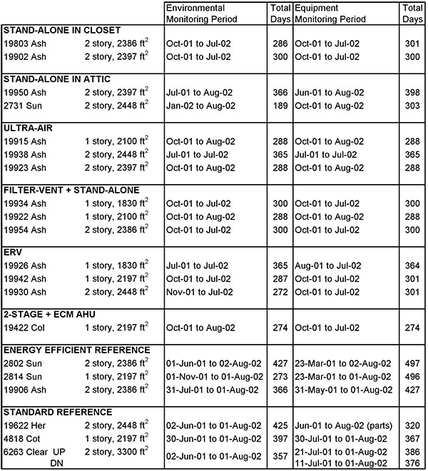
Data collection periods are shown for each house in Table 2. As shown, the monitoring period was not always the same for the environmental conditions and the equipment runtime due to differences in construction completion and occupancy. The house floor area and number of stories is also noted in Table 2.
Table 2: Monitoring periods and size for each house
Results
The incremental first-cost of each system compared to the Standard Reference house is given in Figure 2, broken down by material and installation. As with any research project of this type, the actual production costs may vary from those gathered to perform the study. However, we worked with the suppliers, builder and HVAC contractor to make appropriate judgments relative to production homebuilding.
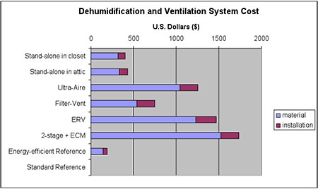
Figure 2: Incremental first-cost, or initial cost, of each ventilation and dehumidification system compared to the Standard Reference house
Figure 3 shows a frequency plot of outdoor environmental conditions during the testing for drybulb temperature, dewpoint temperature, and relative humidity. Drybulb temperature peaked at 107°F and went as low as 27°F, but the bin with the most hours was between 75 and 80 oF. Dewpoint temperature peaked at 82°F and went as low as 4°F; the largest bin, by a large margin, was between 70 and 75°F. Forty percent of the time, outdoor relative humidity was above 85%.
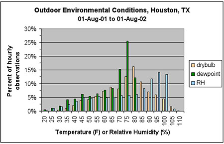
Figure 3: Outdoor environmental conditions from August 2001 to August 2002 . . .
Download complete report here.
Footnotes:
- Lstiburek, J.W., Ph.D., P.Eng, 2002. “Residential Ventilation and Latent Loads,” ASHRAE Journal, Vol. 44, No. 4, April, American Society of Heating, Cooling and Air Conditioning Engineers, Atlanta.
- Lstiburek, J.W., Ph.D., P.Eng, 2002. “Moisture Control For Buildings,” ASHRAE Journal, Vol. 44, No. 2, February, American Society of Heating, Cooling and Air Conditioning Engineers, Atlanta.
- Lstiburek, J.W. 1993. “Humidity control in the humid south.” Workshop Proceedings: Bugs, Mold & Rot II, Building Environment and Thermal Envelope Council.
- Rudd, A.F., J.W. Lstiburek, K. Ueno, 2000. “Unvented-Cathedralized Attics: Where We’ve Been and Where We’re Going.” Proceedings of the 2000 ACEEE Summer Study on Energy Efficiency in Buildings, 23-28 August, Pacific Grove, California. American Council for an Energy Efficient Economy, Washington, D.C.
- Rudd, A.F., J.W. Lstiburek, 1998. “Vented and Sealed Attics In Hot Climates.” Presented at the ASHRAE Summer Annual Meeting, Attics and Cathedral Ceiling Symposium, June, Toronto, Ontario. ASHRAE Transactions TO-98-20-3. American Society of Heating Refrigeration and Air-Conditioning Engineers, Atlanta, GA.
- Rudd, A.F., J.W. Lstiburek, 2001. “Clean Breathing in Production Homes.” Home Energy Magazine, May/June, Energy Auditor & Retrofiter, Inc., Berkeley, CA.
- Rudd, A.F., 1998. “Design/Sizing Methodology and Economic Evaluation of Central-Fan-Integrated Supply Ventilation Systems.” Proceedings of the 1998 ACEEE Summer Study on Energy Efficiency in Buildings, 23-28 August, Pacific Grove, California. American Council for an Energy Efficient Economy, Washington, D.C.